


Barrier MHTM
TM
MicroDrive Access and Parking
Assembly and installation
5815,5013US / Version 05
59
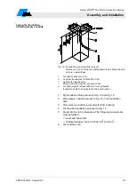
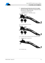
2. Lay the loop carefully into the groove and push it down by
means of a blunt object, such as a piece of wood. The
insulation must by no means be damaged.
3. To avoid slipping of the loop, fix the loop using small wooden
wedges. Remove the wooden wedges later on.
4. Push the loop feed line through the empty conduit in place into
the barrier housing.
5. Measure the induction loop according to chapter 8.4.3.
6. We recommend to cover the inserted loop using quartz sand.
Make sure that at least 0.98 in (25 mm) remain between the
upper edge of the roadway and the quartz sand for the potting
compound.
7. Seal the groove with the potting compound.
The temperature resistance of the loop must match the
temperature of the potting compound.
8. Allow the potting compound to cure.
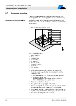
Fig. 19: Installing induction loop in bitumen, asphalt, or concrete
Dimensions in inch are without parenthesis. Dimensions in mm
are in parenthesis.
1
Barrier housing
2
Groove with potting compound
3
Asphalt surface
4
Quartz sand filling
5
Loop cable
6
Foundation
Summary of Contents for MHTM MicroDrive Access Series
Page 4: ...Barrier MHTM TM MicroDrive Access and Parking 4 5815 5013US Version 05...
Page 126: ...Barrier MHTM TM MicroDrive Access and Parking 126 5815 5013US Version 05...
Page 129: ......
Page 130: ...Barrier MHTM TM MicroDrive Access and Parking 130 5815 5013US Version 05...
Page 132: ...Barrier MHTM TM MicroDrive Access and Parking Appendix 132 5815 5013US Version 05...
Page 134: ......
Page 136: ......
Page 138: ......
Page 140: ......


