background image

 S600D USER AND MAINTENANCE MANUAL 


64 

B.


LIQUID COOLING 


The  liquid  cooling  system  ensures  the  optimal  operation  temperatures  of  certain  machine 
components.  This  system  must  be  correctly  maintained  in  order  to  prevent  deterioration  of  the 
equipment. 


The cooling liquid must be replaced annually. 
During maintenance, check for leaks. Power off the machine to check the level of cooling liquid. 
 
To drain the system: 
 

1.


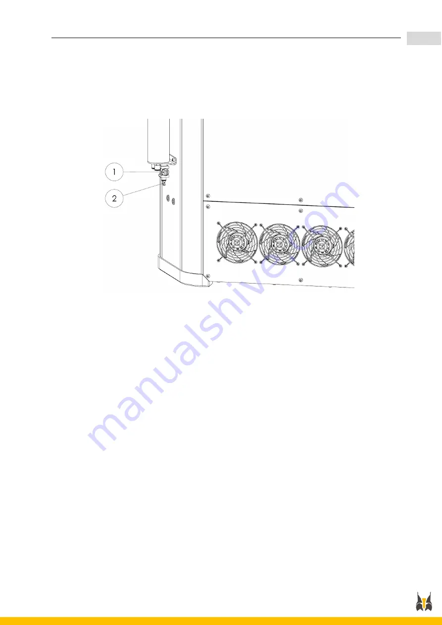
Remove the drain plug (2) on the tap. 

2.


Connect a pipe to the tap. 

3.


Place the other end of the pipe in a container. 

4.


Open the reservoir filler cap (1). 

5.


Turn on the tap and drain all the cooling liquid from the reservoir. 

6.


Turn off the tap. 

7.


Remove the pipe and replace the plug (2) on the tap. 

All manuals and user guides at all-guides.com

Summary of Contents for S600D

Page 1: ...S600D V1 1 All manuals and user guides at all guides com a l l g u i d e s c o m ...

Page 2: ...Animated print preview 21 3 3 4 Web control interface 23 3 3 5 Overview of the touchscreen 29 3 3 6 Regular checks 39 4 Machine 40 S600D 40 4 1 1 Overview 40 4 1 2 Specifications 43 4 1 3 Startup connection and calibration 45 4 1 4 Maintenance 61 5 Filament materials 67 Filament material bay 67 5 1 1 Overview 67 5 1 2 Mounting installation 68 5 1 3 Priming unloading 70 5 1 4 Maintenance servicing ...

Page 3: ...fications 89 6 2 3 Installation 90 6 2 4 Priming and use 92 6 2 5 Unloading 93 6 2 6 Maintenance servicing 94 7 Troubleshooting 98 8 Moving and transporting the machine 101 9 Customer support 102 All manuals and user guides at all guides com ...

Page 4: ...ny defects that the buyer was aware of or that were visible at the time of delivery This warranty will become invalidated if modifications are made or repairs are performed directly or indirectly by the client Our liability is limited to the timely replacement of any parts found to be defective by LYNXTER and excludes all other forms of compensation The customer will bear the cost of any travel ex...

Page 5: ...n risk of burns Coldend The upper portion of the toolhead that is actively cooled to limit heat spreading from the hotend Nozzle Cone shaped metallic part located at the lowest tip of the hotend The diameter of the nozzle determines the extrusion width and restricts the maximal layer height Heated build plate Build platform located in the lower portion of the machine Hot zone hazardous during oper...

Page 6: ...S600D USER AND MAINTENANCE MANUAL 6 All manuals and user guides at all guides com a l l g u i d e s c o m ...

Page 7: ...n place the machine close to an air vent and in an area with low frequentation No special power supply is required Hot zone The hot surface sign indicates the presence of components with high temperatures Always use caution and wear safety gloves when working near hot components Safety footwear not provided When handling the device wear safety shoes to help prevent injuries Gloves not provided Whe...

Page 8: ...ntative may void the warranty Do not modify the environmental conditions in any way that could damage the machine Before using or touching the machine the user or operator must first put on heat resistant safety gloves not supplied Do not lean on the machine Do not interfere with the stability of the machine The machine contains moving parts that are potentially dangerous Never reach inside the ma...

Page 9: ...ANCE MANUAL 9 The power outlet must be easy to access and located close to the machine In the event of an emergency disconnect the power cord of the machine from the power outlet All manuals and user guides at all guides com ...

Page 10: ...oor locking mechanism prevents access to the build area during printing When pressed an indicator light located on the door button uses the following color codes to show the state of the machine o GREEN The door is unlocked press again to open o ORANGE Printing is in progress The door can only be opened if the print job is paused via the control interface Warning some components may still be hot w...

Page 11: ...n STL file Download a model in STL format directly from a repository of 3D models Import and position the STL file s in the 3D printing software Simplify 3D Generate the G code Choose a print profile fff file and define your FFF settings for each of the models Save the G code in a dedicated folder Import the file in the machine via the Web interface Launch the print via the LYNXTER WEB CONTROL INT...

Page 12: ...ort export of files and total control of the machine in optimal conditions 2 Printing directly from the touchscreen on the machine This is the preferred solution for standalone printing No additional devices are required All manuals and user guides at all guides com ...

Page 13: ...de the computer hardware required for the installation The software must be installed on a computer with an Internet connection An Internet connection is needed to download the software installation package and updates subsequently available online If your computer does not have an Internet connection please inform us of this when you place your order and or set up your machine All manuals and use...

Page 14: ...ite You will need the Simplify3D license key received with your machine To begin the installation run the Setup exe file as administrator A window with a setup wizard opens Follow the prompts to set up your machine to work with Simplify3D When the installation is complete you will be required to log in and provide the license key when starting the program for the first time All manuals and user gu...

Page 15: ... are much faster you should control the machine via the Lynxter Web Control interface Ethernet rather than the USB port The USB port is dedicated to accessories Connect the machine to the PC via the Ethernet cable Open the Windows control panel and click on Network and Sharing Center All manuals and user guides at all guides com ...

Page 16: ...NANCE MANUAL 16 In the Active networks section click on Local Area Connection In the Local Area Connection status dialog box click the Properties button All manuals and user guides at all guides com a l l g u i d e s c o m ...

Page 17: ... the machine IP Subnet displayed on the machine interface The computer and the machine must be on the same network in order to connect Ex Machine IP is 192 168 1 10 Subnet is 255 255 255 0 PC IP can be 192 169 1 9 if available PC subnet is 255 255 255 0 You can now save your settings and close all windows by successively clicking OK OK Close X X All manuals and user guides at all guides com ...

Page 18: ...8 1 10 Contact your IT administrator if facing any issues Machine network parameters can be edited from the web interface in the Settings tab The S600D comes with the latest software updates and stable firmware In the event of a major upgrade to either of these we will provide you with the detailed implementation procedure All manuals and user guides at all guides com ...

Page 19: ...file as per the process settings applied to the models For multiple processes be sure to specify if printing should be continuous or sequential part by part 6 Interactive display showing the 3D view of the STL files in the build area 7 Cross section view of the selected models machine control panel not used and automatic generation of support structures 8 Display settings for the models on the bui...

Page 20: ... quality and extruder You can also adjust the interior solidity of your model by changing the Infill Percentage as well as generate a raft and or support structures Click Select Models to select the models to which these settings will be applied Click Show Advanced to display and configure the settings in more detail All manuals and user guides at all guides com ...

Page 21: ...d material properties and print settings for bridges unsupported areas Advanced Settings to apply the process to specific layers of the model procedures to repair mesh errors travel movement rules and tool change options Click the Prepare to Print button and select the processes models to print if necessary The G code simulator preview mode appears You can switch between the virtual build table an...

Page 22: ...xtruder number and nozzle diameter to avoid accidently printing with the wrong material This same organization can be replicated when using the folder creation feature in the G code file manager on the Lynxter Web Control interface Example PLA R KMY Red E0 N040 lynxter gcode All manuals and user guides at all guides com ...

Page 23: ...twork or to a computer via an Ethernet cable A CONNECTING AND LOADING A TOOLHEAD Access the machine IP from a web browser Mozilla Firefox preferred When you connect to the web interface a screen for loading a toolhead appears 1 Mount the toolhead of your choice in the machine see 5 2 3 or 6 2 3 if this has not already been done 2 Via the interface select the type and model of the toolhead that is ...

Page 24: ...isible at all times 1 Window showing the movements of the machine 2 G code entry field to send a G code command to the machine 3 Window to view or modify the operating temperatures of the different machine components This is also where you should unload a toolhead before changing it 4 Emergency stop button 5 Multi tab window for details see section 3 3 4 C All manuals and user guides at all guides...

Page 25: ...respectively Use with caution launch machine and nozzle height calibration procedures Reduced versions of the MACROS and GCODES tabs see details below are located on the right hand side of the dashboard A window for communicating directly with the machine by sending G code commands See https duet3d dozuki com Wiki Gcode for a list of possible commands Displays the mesh calibration Settings for bed...

Page 26: ...t the layer height in 0 05 mm increments 3 Layer chart real time chart showing the time spent for each layer printed 4 Sliders for real time modification of print settings such as extrusion rate print speed or fan control Here you can view the G code files loaded on the machine These are the files of the parts to print 1 1 1 1 3 1 1 1 4 1 1 1 Add a program to the directory 2 All manuals and user g...

Page 27: ...vent of an error Lynxter is not liable for damage caused by modifications to system files Here you can modify and add machine configuration files Internal machine functions can be freely accessed For development purposes system configuration files are not protected Be sure to keep a copy of the original configuration files in the event of an error Lynxter is not liable for damage caused by modific...

Page 28: ...nection settings for remote monitoring of print jobs In this tab you can modify the values displayed in the machine s different buttons and drop down lists List items and babystep The diagnostics button can be used to perform machine system diagnostics Here you can adjust XY tool offsets and tilt compensation values see 4 1 3 C and E All manuals and user guides at all guides com ...

Page 29: ...ough certain machine settings are not available A CONNECTING AND LOADING A TOOLHEAD When you power on the machine a screen for loading a toolhead appears 1 Mount the toolhead of your choice in the machine see 5 2 3 or 6 2 3 if this has not already been done 2 Via the interface select the type and model of the toolhead that is in the machine Button to load calibration tool Type of toolhead All manu...

Page 30: ...ouchscreen does not display any parts of the screen permanently The menu shown below allows you to navigate between the different display windows of the touchscreen To display this menu click the button at the top left of the screen All manuals and user guides at all guides com ...

Page 31: ...t tab of this window allows you to view and control the operating temperatures of the different components The second tab shows the programs loaded on the machine See G CODE FILES window All manuals and user guides at all guides com a l l g u i d e s c o m ...

Page 32: ...t real time chart showing the operating temperatures of the different machine components 2 Layer chart real time chart showing the time spent for each layer printed 3 Babystepping to adjust the layer height in 0 05 mm increments 4 Play pause to pause resume or cancel a print job 1 1 1 1 1 1 1 1 1 1 1 1 All manuals and user guides at all guides com ...

Page 33: ...3 Tab to view or adjust the operating temperatures of the different machine components This is also where you unload a toolhead before changing it 4 Tab to control extrusion speed 5 Tab to move the toolhead 6 Fan control 7 View of the macros loaded on the machine See macros below 3 All manuals and user guides at all guides com ...

Page 34: ...S600D USER AND MAINTENANCE MANUAL 34 To consult and execute the programs loaded on the machine All manuals and user guides at all guides com ...

Page 35: ...S600D USER AND MAINTENANCE MANUAL 35 Displays the mesh calibration Settings for bed leveling compensation All manuals and user guides at all guides com ...

Page 36: ...ANUAL 36 A window for communicating directly with the machine by sending G code commands See https duet3d dozuki com Wiki Gcode for a list of possible commands All manuals and user guides at all guides com a l l g u i d e s c o m ...

Page 37: ...ernal machine functions can be freely accessed For development purposes system configuration files are not protected Be sure to keep a copy of the original configuration files in the event of an error Lynxter is not liable for damage caused by modifications to system files All manuals and user guides at all guides com ...

Page 38: ...S600D USER AND MAINTENANCE MANUAL 38 Here you can adjust XY tool offsets and tilt compensation values see 4 1 3 C and E All manuals and user guides at all guides com ...

Page 39: ...uild plate Check that the build plate is clean and smooth 3 Check cooling Run the cooling test macro and check that the three fans on the toolhead operate for 30 seconds You should feel a light breeze under the extrusion nozzles 4 Check the tension of the filament in the extruder Disconnect the extruder tubing Insert a filament into the extruder so that it protrudes by several centimeters Use the ...

Page 40: ...ring Center also known as a 3D printer It can be used with different types of toolheads and can build parts made of different materials This manual provides instructions for the operation and maintenance of the S600D 3D printer All manuals and user guides at all guides com ...

Page 41: ...S600D USER AND MAINTENANCE MANUAL 41 All manuals and user guides at all guides com a l l g u i d e s c o m ...

Page 42: ...l 2 Door 3 Door release button 4 Liquid cooling reservoir 5 Heat exchanger 6 220V power connector 7 Tool gauge port 8 Ethernet port 9 USB port 10 Material bay 11 Air filtration vent All manuals and user guides at all guides com ...

Page 43: ...ge recovery function Standalone touchscreen and Web interface Ethernet 851 L x 913 W x 1644 H mm Quick mechanical and electronic connectors liquid cooled 12 5 μm 12 5 μm 12 5 μm Modular Heated build plate 20 C to 200 C Build chamber 20 C to 80 C Liquid cooled toolhead HEPA H14 activated carbon filtration Locked machine access Standard G code Lynxter S600D firmware based on RepRapFirmware All manua...

Page 44: ...S600D USER AND MAINTENANCE MANUAL 44 230V AC 16A 50 60Hz All manuals and user guides at all guides com ...

Page 45: ... electrical hazards and damage to the equipment Connect the machine to an easily accessible and nearby 230V 10A power outlet For Ethernet connection Connect one end of the RJ45 cable to the Ethernet port 2 on the machine Connect the other end of the cable to a network port computer server LAN etc For USB connection not required if you are going to control the machine via the Lynxter Web Control in...

Page 46: ...is calibration tool in the toolholder 6 Connect the toolhead quick connector inside the machine 7 Connect to the machine via the Web control interface see Network deployment 8 Load the calibration tool via the Web control interface see 3 3 4 A 9 Launch a Delta calibration via the Dashboard tab Two calibration procedures will begin automatically Geometric calibration and surface calibration 10 When...

Page 47: ...dule Use this tool to orient the Z axis so that it is perpendicular to the build surface This will ensure that material is deposited in a regular and uniform manner on the build plate To access this tool WebControl Settings calibration To enter a value Press Enter to validate To adjust the value in increments of 0 01 or To modify the tilt displayed in or value Z distance for 100 mm of X or Y offse...

Page 48: ...ther than both at once which could introduce combined errors To begin calibration prepare the XY Tilt calibration stl file supplied for printing Configuration required FIL33 HF Toolhead N040 Nozzle Layer height 0 3 mm The tilt of the XY plane is normalized and obeys the following rules Rotation around the X axis is labelled A Its value is positive and rotation is clockwise Rotation around the Y ax...

Page 49: ...UAL 49 Flattening in X lifting in X Orient Z by performing a rotation around Y Tilt B in a counterclockwise towards X direction Use 0 05 increments to begin with then adjust if necessary All manuals and user guides at all guides com ...

Page 50: ...MANUAL 50 Flattening in X lifting in X Orient Z by performing a rotation around Y Tilt B in a clockwise towards X direction Use 0 05 increments to begin with then adjust if necessary All manuals and user guides at all guides com ...

Page 51: ...attening in Y lifting in Y Orient Z by performing a rotation around X Tilt A in a clockwise towards Y direction Use 0 05 increments to begin with then adjust if necessary All manuals and user guides at all guides com a l l g u i d e s c o m ...

Page 52: ...ements to begin with then adjust if necessary A full calibration using the geo surf calibration tool must first be performed Mount the tool specify the thermal environment of the machine temperature of the build plate and chamber max 45 C then launch the calibration procedure by clicking Delta Calibration in Machine movement All manuals and user guides at all guides com ...

Page 53: ...eling via the Web interface The leveling process is automatic The toolhead will position itself at mid height inside the build chamber 7 When leveling process is complete disconnect the calibration gauge from the port 8 Remove the calibration gauge from the build plate The toolhead is now calibrated E XY OFFSET CALIBRATION MULTI MATERIAL TOOLHEADS Objective To manually compensate absolute relative...

Page 54: ...lt compensation and babystep and the nozzles must be leveled Nozzle height calibration macro and placed in position against the silicon disc to prevent leaks Materials must be pre loaded and primed pre load then prime macros For a different configuration materials nozzles etc a different g code file must be generated To begin calibrating the nozzle connected to E1 import the XY Tool offset calibra...

Page 55: ...caliper micrometer principle we will deduce the nozzle offset modification value by comparing the alignment of the offset and ref parts The target result is as follows We will define the study areas as follows 0 05mm 0 10mm 0 15mm 0 20mm 0 25mm 0 30mm 0 35mm 0 40mm 0 45mm 0 50mm 0 00mm Y Y X X All manuals and user guides at all guides com ...

Page 56: ...th bar from the center in the direction of X It corresponds to an offset of 0 25 mm 5 x 0 05 mm We must therefore decrease the travel distance of T1 on X decrease the absolute value of offset X from 19 25 mm to 19 00 mm Compensate by adding 0 25 mm to T1 on Offset X X X All manuals and user guides at all guides com a l l g u i d e s c o m ...

Page 57: ...enter in the direction of X It corresponds to an offset of 0 15 mm 3 x 0 05 mm We must therefore increase the travel distance of T1 on X increase the absolute value of offset X from 19 25 mm to 19 40 mm Compensate by adding 0 15 mm to T1 on Offset X X X All manuals and user guides at all guides com ...

Page 58: ...enter in the direction of Y It corresponds to an offset of 0 15 mm 3 x 0 05 mm We must therefore decrease the travel distance of T1 on Y decrease the absolute value of offset Y from 11 00 mm to 10 85 mm Compensate by adding 0 15 mm to T1 on Offset Y Y Y All manuals and user guides at all guides com ...

Page 59: ...enter in the direction of Y It corresponds to an offset of 0 25 mm 5 x 0 05 mm We must therefore increase the travel distance of T1 on Y increase the absolute value of offset Y from 11 00 mm to 11 25 mm Compensate by adding 0 25 mm to T1 on Offset Y Y Y All manuals and user guides at all guides com ...

Page 60: ...S600D USER AND MAINTENANCE MANUAL 60 All manuals and user guides at all guides com ...

Page 61: ...e the user or operator must first put on heat resistant safety gloves Ensure that the 3D printer is not in operation Wait until the main LED goes off Put on heat resistant safety gloves not supplied Unscrew the screws of the build plate Pull it forwards to remove it All manuals and user guides at all guides com a l l g u i d e s c o m ...

Page 62: ...ould provide the filter reference numbers Number Description 3 Activated carbon filter 4 HEPA 14 filter To remove and replace the filters 1 Power off the machine 2 On the top of the machine unscrew the 9 screws E1 of the cover panel 1 Number Description E1 9 BHC screws 1 Cover panel 3 Remove the cover panel 1 4 Unscrew the 8 screws E2 of the fan plate 2 with the ALLEN wrench supplied All manuals a...

Page 63: ...t the fan power supply connector 6 Remove the fan plate 2 7 Remove the first filter HEPA 3 followed by the second activated carbon filter 4 8 Install two new filters in the same positions and order 9 Replace the fan plate and the cover panel of the machine 10 Reconnect the fan power supply connector All manuals and user guides at all guides com ...

Page 64: ... be replaced annually During maintenance check for leaks Power off the machine to check the level of cooling liquid To drain the system 1 Remove the drain plug 2 on the tap 2 Connect a pipe to the tap 3 Place the other end of the pipe in a container 4 Open the reservoir filler cap 1 5 Turn on the tap and drain all the cooling liquid from the reservoir 6 Turn off the tap 7 Remove the pipe and repla...

Page 65: ... 2 liters To fill the reservoir 1 Check that the tap is in the closed position 2 Unscrew the cap 1 at the top of the reservoir 3 Insert a funnel into the filler cap hole and fill the reservoir up to the indicator line with the cooling liquid supplied by the manufacturer 4 Screw the cap 1 back on All manuals and user guides at all guides com ...

Page 66: ...lide the platform in the appropriate direction in order to spread the grease Slide rails should be greased at least once a year Figure 1 Lubrication kit Figure 2 Grease cartridge Figure 3 slide rail NUMBER REFERENCE DESCRIPTION 1 DS2016 SP 011 Lubrication kit 2 DS2016 SP 012 Grease cartridge All manuals and user guides at all guides com a l l g u i d e s c o m ...

Page 67: ...both the material bay and the toolhead The material bay must be used with toolheads that use the same manufacturing process In this case filament toolheads The material bay is equipped with three lines of cooled bowden extrusion with filament sensors The main electrical wiring cable runs between the material bay and the toolhead All manuals and user guides at all guides com ...

Page 68: ...se 4 Use the handles to pull and remove the material bay from the machine 5 Mount the filament material bay into position with the help of the guide brackets 8 Push it in until it touches the wall of the machine LABEL DESCRIPTION 1 Knurled nuts 2 Extrusion blocks 3 Filament sensors 4 Bowden fan 5 Quick connect electrical connecter link to the machine 6 Quick connect electrical connector link to th...

Page 69: ...ighten the 4 knurled nuts 1 7 Power on the machine 8 You can now mount a toolhead that is compatible with the filament material bay see section 5 2 3 and then load the filament see section 5 1 3 8 All manuals and user guides at all guides com ...

Page 70: ...ff and that both the filament material bay and filament toolhead are correcty installed If this is not the case see sections 5 1 2 and 5 2 3 2 Position the filament spool 2 on the spool holder 1 Number Description 1 Spool holder 2 Spool 3 S600D printer All manuals and user guides at all guides com ...

Page 71: ...Fully insert the filament into the lower entry port the filament run out sensor 1 It must reach the extruder 2 and should remain in place on its own once inserted 5 Via the control interface run the Pre Load Filament macro Web interface Macro materials Filament Pre load E_x Pointed end of filament All manuals and user guides at all guides com a l l g u i d e s c o m ...

Page 72: ...Web interface Macro filament PC Prime E_x This macro will get the heater block up to temperature and continue to push the filament until it extrudes This macro must therefore be adapted for each different material extrusion temperatures 7 You should now be able to see the filament extruding All manuals and user guides at all guides com ...

Page 73: ... E_x macro web interface Macro filament PC unload E_x 3 If the filament does not come out of the extruder completely loosen the thumbscrew tensioner 1 on the side of the extruder 4 Then pull on the filament to extract it completely 5 Tighten the thumbscrew 1 to reset the tension of the extruder 1 All manuals and user guides at all guides com ...

Page 74: ... Unload the filament from the extruder via the control interface see Unloading material 5 1 3 B 2 Disconnect the upper PTFE tubing by pushing the top collar 18 down and pulling the tube up and out 19 at the same time 3 Loosen the screws E1 that attach the extruder to the frame 4 Remove the extruder 1 from the frame Remove the screws E1 4 All manuals and user guides at all guides com ...

Page 75: ...75 5 Place the extruder 1 upside down on a flat surface 6 Open the extruder 1 by separating the black case 11 and 12 7 Remove the pin 13 from the housing then remove the part on the side 14 All manuals and user guides at all guides com ...

Page 76: ...eels 16 to remove all plastic debris 9 Put all pieces of the extruder back together by following this procedure in reverse order 10 Put the extruder 1 back on the frame 11 Insert the PTFE tubing 19 back into the top collar 12 Repeat this procedure for the two other extruders 16 15 19 All manuals and user guides at all guides com a l l g u i d e s c o m ...

Page 77: ...ad has three extrusion nozzles and can therefore print parts in three different materials 3 separate filament extrusion lines Ø1 75 mm Filament run out detection Maximum extrusion temperature 450 C Automatic nozzle height calibration Material flow ooze control system and automatic nozzle wipe Modular nozzle diameters and materials Ø0 15 mm to Ø1 2 mm All manuals and user guides at all guides com ...

Page 78: ...pen the door of the machine 4 Get the triple extrusion toolhead ready 5 Mount the toolhead on the toolholder Position the toolhead so that the liquid cooling couplings are at the back 6 Connect the two liquid cooling tubes and the main cable quick connector for the material supply and electrical wiring of the toolhead inside the machine All manuals and user guides at all guides com ...

Page 79: ...onnect the liquid cooling bypass tube supplied to this fitting Tighten the 4 thumbscrews that attach the toolhead to the toolholder 8 Load the toolhead via the control interface see section 3 3 4 A 9 Prime the filament see section 5 1 3 10 The toolhead is now installed 11 You must now calibrate the nozzle height and XY offsets see sections 4 1 3 D and 4 1 3 E 1 2 All manuals and user guides at all...

Page 80: ...procedure for unloading the filament see section 5 1 3 B 14 To initiate the procedure for unloading the toolhead click the unload tool button on the touchscreen 15 Open the door of the machine 16 Disconnect the main cable quick connector electrical and hydraulic 17 Unscrew the thumbscrews on the toolhead 18 Remove the toolhead from the machine All manuals and user guides at all guides com ...

Page 81: ...and printer components are cool 3 Proceed to the toolhead unloading see 5 2 4 4 Remove the oozing platform at the bottom of the toolhead by unscrewing the central screw 5 Disconnect the two connectors linked to the extrusion block of the nozzle that you wish to remove as shown in the image below To avoid damage lift up the tongue of the connector before pulling 6 Use the Allen wrench supplied to u...

Page 82: ...n block 1 2 3 4 5 has been separated from the cooling block 6 unscrew the nozzle 1 and clean it Number Description 1 Extrusion nozzle 2 Heater block 3 Heater cartridge 4 PT100 sensor 5 Heatsink 6 Cooling block 7 All manuals and user guides at all guides com ...

Page 83: ...er on the machine 10 You must now calibrate the nozzle height see section 4 1 3 D EXTRUDER BLOCK ASSEMBLY In some cases further cleaning might be required Follow these steps to mount dismount completely the extrusion block 1 Place le heatsink opposite its inlet as shown in the photo below 2 Screw the heatsink into the inlet until the top of the thread just touches the surface All manuals and user ...

Page 84: ...rew the nozzle into the inlet opposite the heatsink until it won t go any further 4 Place the assembled block in a vise and tighten the vise to hold the heater block being careful not to damage it All manuals and user guides at all guides com ...

Page 85: ... heatsink in place 6 Position the heater cartridge as shown in the photo below foot of the connector on the nozzle side and centrally placed when compared to the heater block 7 Securely tighten the BHC screw supplied so that the heater cartridge is held in position by the deformed block All manuals and user guides at all guides com ...

Page 86: ...ding inlet the same way round as the heater cartridge 9 Carefully tighten the grub screw supplied so that it just touches the temperature sensor Warning over tightening the grub screw may result in damage to the PT100 sensor All manuals and user guides at all guides com a l l g u i d e s c o m ...

Page 87: ...toolheads The material bay is equipped with two pneumatic outlets for the liquid deposition toolheads and requires a compressor not supplied maximum pressure 8 bars The main electrical wiring cable runs between the material bay and the toolhead Knurled nuts Manometer outlets 1 and 2 Pressure settings for outlets 1 and 2 Manometer air supply Quick connect electrical connecter link to toolhead Quick...

Page 88: ...e case 4 Use the handles to pull the material bay out of the machine 5 Install the liquid material bay with the help of the guide brackets 8 Push it in until it touches the wall of the machine 6 Tighten the 4 knurled nuts 1 7 Power on the machine 8 Connect the air inlet to a compressor not pressurized 9 You can now mount a toolhead that is compatible with the liquid material bay see section 6 2 3 ...

Page 89: ... a quick connect fitting Single component fluids Viscosity 10 3 Pa s to 2000 Pa s Volumetric flow 0 03 to 3 3 ml min or 0 05 to 5 5 ml min High volumetric precision High chemical resistance Precise flow start and end points Easy to dismantle and clean Interchangeable nozzles Ø0 2 mm to Ø1 6 mm Maximum dosing pressure 20 bars internal pressure different than input pressure All manuals and user guid...

Page 90: ...e 2 Wait until the main LED goes off 3 Open the door of the machine 4 Get the liquid toolhead ready 5 Mount the toolhead on the toolholder Position the toolhead so that the material cartridge is facing towards you All manuals and user guides at all guides com ...

Page 91: ...material bay see section 6 1 2 7 Tighten the 4 thumbscrews on the toolhead 8 Load the toolhead via the control interface see section 3 3 4 A 9 The toolhead is now installed but not yet pressurized 10 Prime the toolhead see section 6 2 4 11 Calibrate the nozzle height see section 4 1 3 D All manuals and user guides at all guides com a l l g u i d e s c o m ...

Page 92: ...e control tab see section 3 3 5 Set the extrusion speed to maximum 5 mm s to save time The material will be dispensed from the tip of the toolhead where you will mount the nozzle 7 Mount the nozzle into position on the tip of the toolhead and continue extruding until the material flows from the nozzle If you want to fill your own serynges please follow these steps It is always preferable to use a ...

Page 93: ... supply to the material bay Check the manometer 2 readings to be sure that the pressure in the pneumatic circuit is at 0 3 Open the door of the machine 4 Disconnect the main cable quick connector 5 Unscrew the thumbscrews on the toolhead 6 Remove the toolhead from the machine 7 Always clean the toolhead after use see section 6 2 6 All manuals and user guides at all guides com ...

Page 94: ... after use to prevent reticulation of material inside the toolhead 1 Remove the toolhead see section 6 2 5 2 Remove the liquid pump from the toolhead Disconnect the tube from the connector by pressing down on the collar and gently pulling the tube All manuals and user guides at all guides com ...

Page 95: ...UAL 95 4 Unscrew the 3 grub screws and separate the pump into two parts 5 Unscrew the three previously hidden screws in the black part of the pump then unscrew and remove this black part All manuals and user guides at all guides com ...

Page 96: ...R AND MAINTENANCE MANUAL 96 6 Clean the eccentric screw 7 Remove the nozzle holder from the body of the pump and clean any residu al material All manuals and user guides at all guides com a l l g u i d e s c o m ...

Page 97: ...S600D USER AND MAINTENANCE MANUAL 97 8 When clean put the toolhead back together by following this procedure in reverse order All manuals and user guides at all guides com ...

Page 98: ... then reconnect the machine from the power supply If the problem persists contact customer support Check the target temperature of the nozzles on the control panel If heating is disabled the machine is in safety mode Turn the machine off and then back on again If the problem re appears contact customer support If the temperatures of the nozzles are normal stop printing and unload the filament Foll...

Page 99: ...ayer height in the print settings experienced user Check that the extruders are not clogged up If this is the case follow the procedure for cleaning the extruders If the problem persists reduce the print speed elevate extrusion temperature and or adjust extrusion multiplier width experienced user Adjust extrusion multiplier width experienced user Stringing and nozzle oozing can occur for several r...

Page 100: ...lem persists reduce the print speed If the problem you are experiencing does not appear in this table or if you cannot resolve it by following one of the solutions proposed contact customer support If you wish to further develop your knowledge of the S600D 3D printer or your 3D printing skills we can provide training sessions Contact customer support for details All manuals and user guides at all ...

Page 101: ...tive who has obtained the manufacturer s permission to transport the machine In the event that the buyer customer or operator decides to move the machine any damage that may arise during or as a result of transit will not be covered by the manufacturer All manuals and user guides at all guides com a l l g u i d e s c o m ...

Page 102: ...company name Your telephone number The model of the product The serial number the machine and devices A detailed description of the problem encountered If possible you should be next to the machine when contacting customer support For advanced troubleshooting please provide the following by email STL files gcodes and screenshots Detailed photos illustrating the problem All manuals and user guides ...

Page 103: ...S600D USER AND MAINTENANCE MANUAL 103 Technocité Atelier 4 9 rue Pierre Georges Latécoère 64100 Bayonne FRANCE contact lynxter fr 33 0 5 64 11 11 21 All manuals and user guides at all guides com ...

Page 104: ...S600D USER AND MAINTENANCE MANUAL 104 All manuals and user guides at all guides com ...

Reviews: