


Chapter 8 Modbus Communication
8-1
8.1 Modbus Communication
8.1 Introduction
PLC option card of iS7 inverters’ built-in communication supports Modbus, the Modicon
product’s communication protocol. It supports ASCII mode, using ASCII data and RTU mode
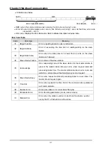
using Hex data. Function code used in Modbus is supported by instruction and especially
function code 01, 02, 03, 04, 05, 06, 15 and 16. Refer to "Modicon Modbus Protocol Reference
Guide"
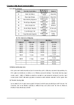
8.1.2 Basic Specification
1) ASCII Mode
(1) It communicates, using ASCII data.
(2) Each frame uses ': (colon: H3A)', for header, CRLF (Carriage Return-Line Feed : H0D
H0A), for tail.
(3) It allows Max. 1 second interval between characters.
(4) It checks errors, using LRC.
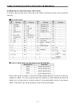
(5) Frame structure (ASCII data)
Item
Header
Address
Function
code
Data
LRC
Tail
(CR/LF)
Size
1 byte
2 bytes
2 bytes
n bytes
2 bytes
2 bytes
2) RTU mode
(1) It communicates, using hex data.
(2) There's no header and tail. It starts with address and finishes frame with CRC.
(3) It has at least 3.5 character times between two frames.
(4) It ignores the current frame when 1.5 character times elapse between characters.
(5) It checks errors, using 16 bit CRC.
(6) Frame structure (hex data)
Item
Address
Function code
Data
CRC
Size
1 byte
1 bytes
n bytes
2 bytes
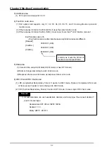
1) The size constituting 1 letter is 1 character. So 1 character is 8 bits that is 1 byte.
2) 1 character time means the time lapsed for sending 1 character.
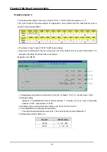
Ex) Calculation of 1 character time at 1200 bps.
1200 bps means that it takes 1 second to send 1200 bits.
To send 1 bit, 1 sec/1200 bits = 0.83 ms.
Therefore, 1 character time is 0.83ms * 8 bits = 6.64ms.
3) 584, 984 A/B/X executes frame division, using intervals of more than 1 sec without LRC
in processing internally.
Remark


