


Chapter 7 Exclusive Functions for iS7 Inverter Control/Monitoring
7-11
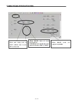
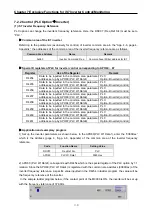
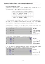
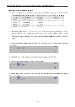
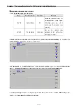
3) In the ladder program below, when the M0002 contact is ON, the inverter operates forward at the
frequency of 11.52Hz (frequency 11.52Hz reference from keypad).
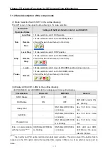
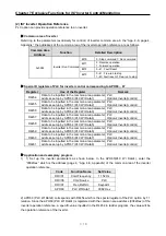
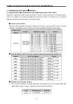
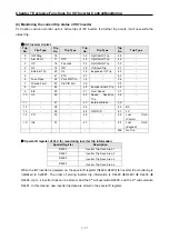
(3) Using inverter digital output contact points (basic 10: 3 points, with 10 extensions: basic
10 + 3 points) as the digital output contact points of PLC option.
◎
Number of output contact points (iS7 internal output extended IO output points)
Type
Number of Digital Output points
Basic I/O/O
2 points (Relay 1point (TR output)
Expansion I/O
3points (Relay output)
Total points
6 points
The digital output points (relay output contact points) of PLC option is 4 points. If more digital output points
are required, you can make use of extended digital output points (3 relay output points) in addition to the
points (2 relay points, 1 TR points) built in the inverter. In detail, in addition to the 4 basic digital output points
(relay outputs) built-in the PLC option card, 6 output points (9 relay points, 1 TR point) comprising the 3 basic
digital output points (2 relay points, 1 TR point) built-in the iS7 inverter and the 3 relay output points of the
extension I/O board are available for the PLC option.
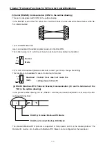
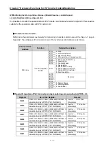
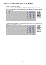
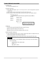
▶
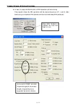
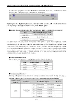
Inverter parameter setting
The inverter digital output to be used by the PLC option must be set to “None.”
Code
Function Name
Set Value
OUT31
Relay 1
None
OUT32
Relay 2
None
OUT33
Q1 None
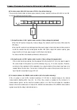
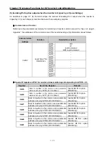
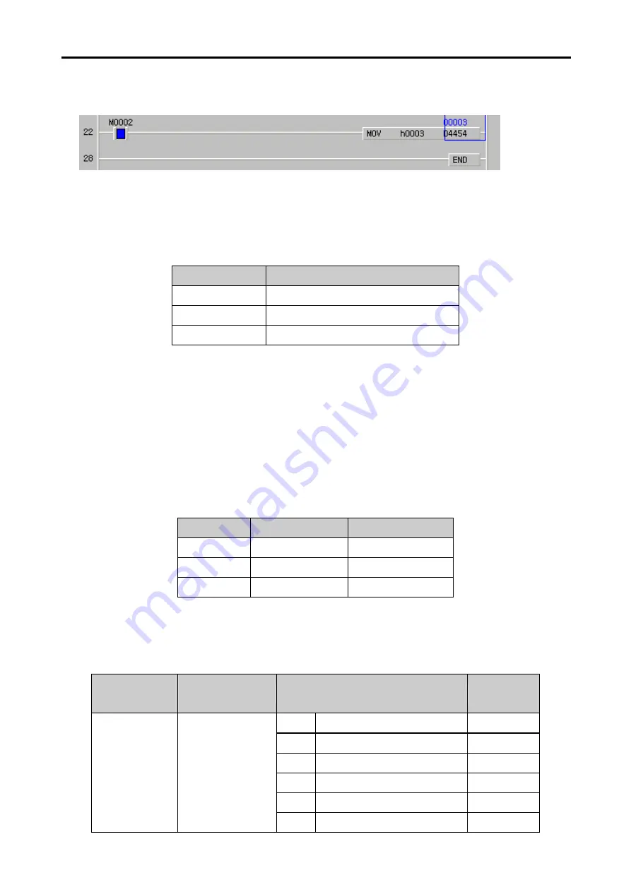
▶
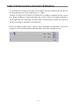
Common area of inverter
Referring to the parameters (exclusively for control) of inverter common area in the “App. 4-6, page 4,
Appendix,” the addresses of the common area of the inverter’s digital outputs are as follows.
Common Area
Address
Function
Detailed Description
Remark
BIT0
0: Relay1 OFF 1: Relay1 ON
0x0386
BIT1
0: Relay2 OFF 1: Relay2 ON
BIT2
0: Q1 OFF 1: Q1 ON
BIT3
0: Q2 OFF 1: Q2 ON
BIT4
0: Q3 OFF 1: Q3 ON
0x0386
Inverter Digital
Output
BIT5
0: Q4 OFF 1: Q4 ON


