


Chapter 8 Modbus Communication
8-6
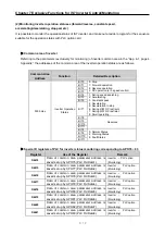
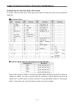
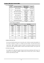
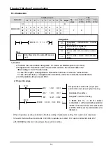
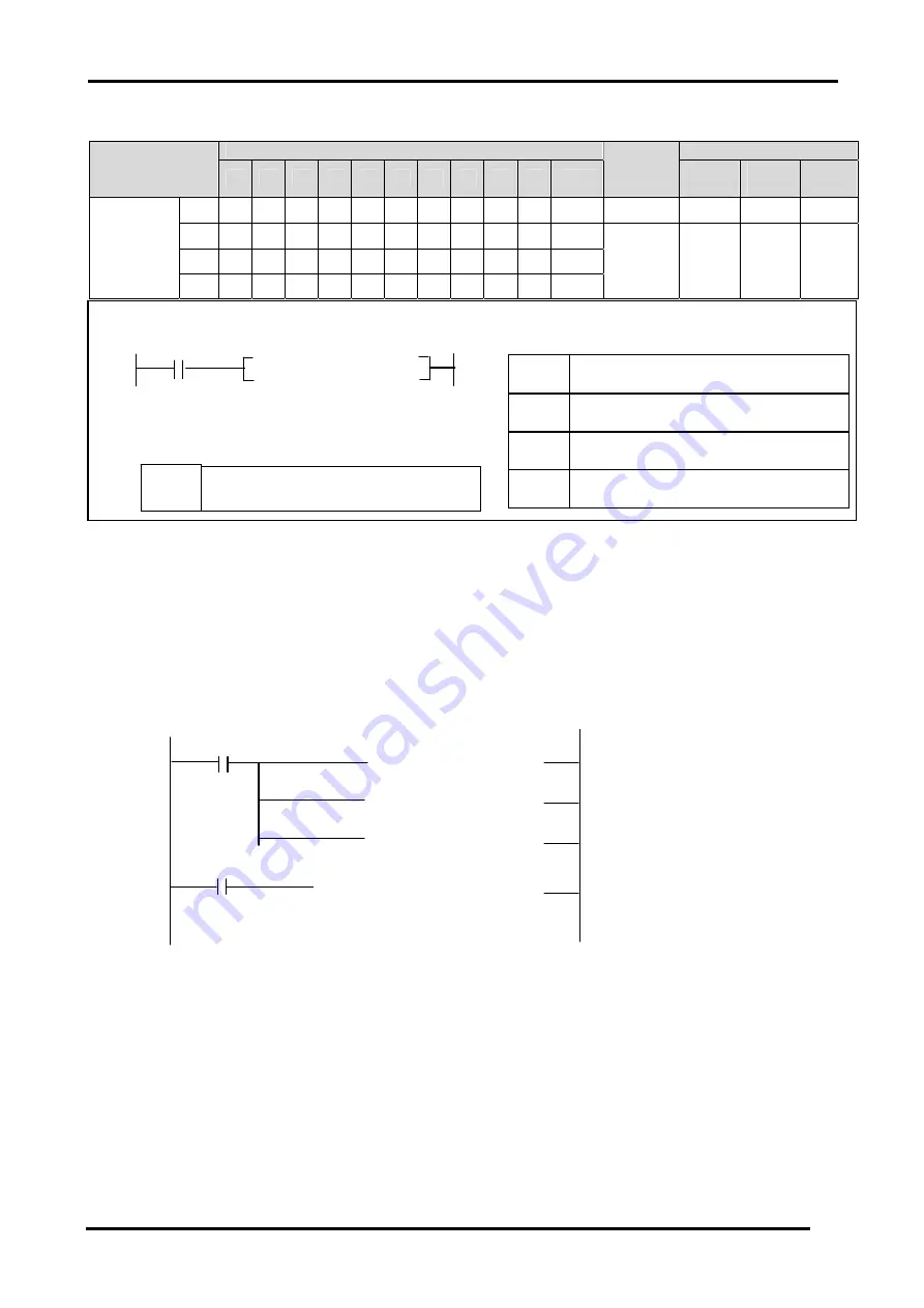
8.1.4 Instruction
Available device
Flag
Instruction
M P
K L F T
C
S
D
#
D integer
No. of
steps
Error
(F110)
Zero
(F111)
Carry
(F112)
Ch
O
S1 O O O O O O
O
O
O
S2 O O O O O
O
O
O
MODCOM
S3 O O O O O
O
O
O
7 O
`
1) Function
•
It transfer the saved data in designated S1 device via Modbus protocol. (3 Word)
•
Designates the first address of the device which will store the received data in S2.
Î
According to the S1 function code,
In case of reception, it designates the first address of device to store the received data.
In case of transmission, it designates the first address of device to store the trasmitted data.
•
Communication status is saved in S3.
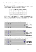
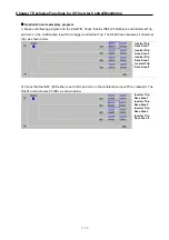
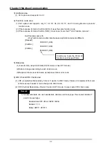
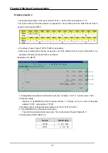
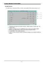
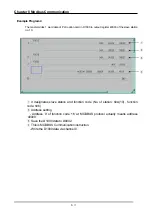
2) Program Example
When it operates as slave selected in Modbus setting of parameter setting, PLC option card responses
to master station without commands. And When operates as master, PLC option card sends data in S1
with MODBUS protocol at rising edges of execution condition.
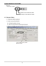
MODCOM Ch S1 S2 S3
Designation
[ MOV h0025 D0002 ]
[ MOV h0013 D0001 ]
[ MOV h0301 D0000 ]
[ MODCOM 1 D0000 D1000 M100 ]
M0020
F0012
Designate slave station No. (Upper byte)
and Function code (Lower byte) of reading.
Designates number of reading.
If M0020 turns On, it start the Modbus
communication with stored modbus parameter
in D000 via Channel 1 and save the received data
at D1000. M100 saves the communication error
information
Designates the address.
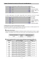
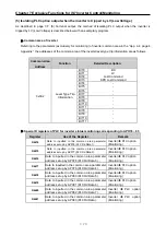
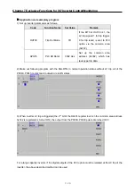
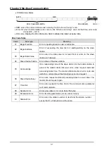
Flag
S1
Device which is registered
communication parameter
S2
Device which stored communication
data
S3
Device which stored communication
status
Ch
Designated communication channel
(Ch 0, Ch 1)
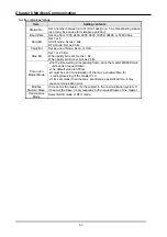
F110
Error flag turns On when #D area is
over.


