

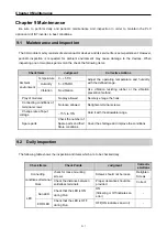
Chapter 8 Modbus Communication
8-8
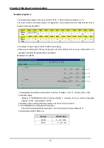
Example Program 1
The master reads status of the Coil 00020 ~ 00056 of the slave station no. 17. The Coil of the slave
station is supposed to be as follows and the data that are read is saved in data register D1000.
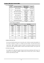
Coil
59
58
57
56
55
54
53
52
51
50
49
48
47
46
45
44
43
42
41
40
Status
X X X 1 1 0 1 1 0 0 0 0 1 1 1 0 1 0 1 1
Hex
1 B 0 E B
Hex
39
38
37
36
35
34
33
32
31
30
29
28
27
26
25
24
23
22
21
20
Status
0 0 1 0 0 1 1 0 1 0 1 1 1 1 0 0 1 1 0 1
Hex 2
6
B C D
The status of Coil 57, 58, 59 is redundancy.
Data is sent starting from the low bit by byte unit. If the deficient bit of a byte is filled with 0.
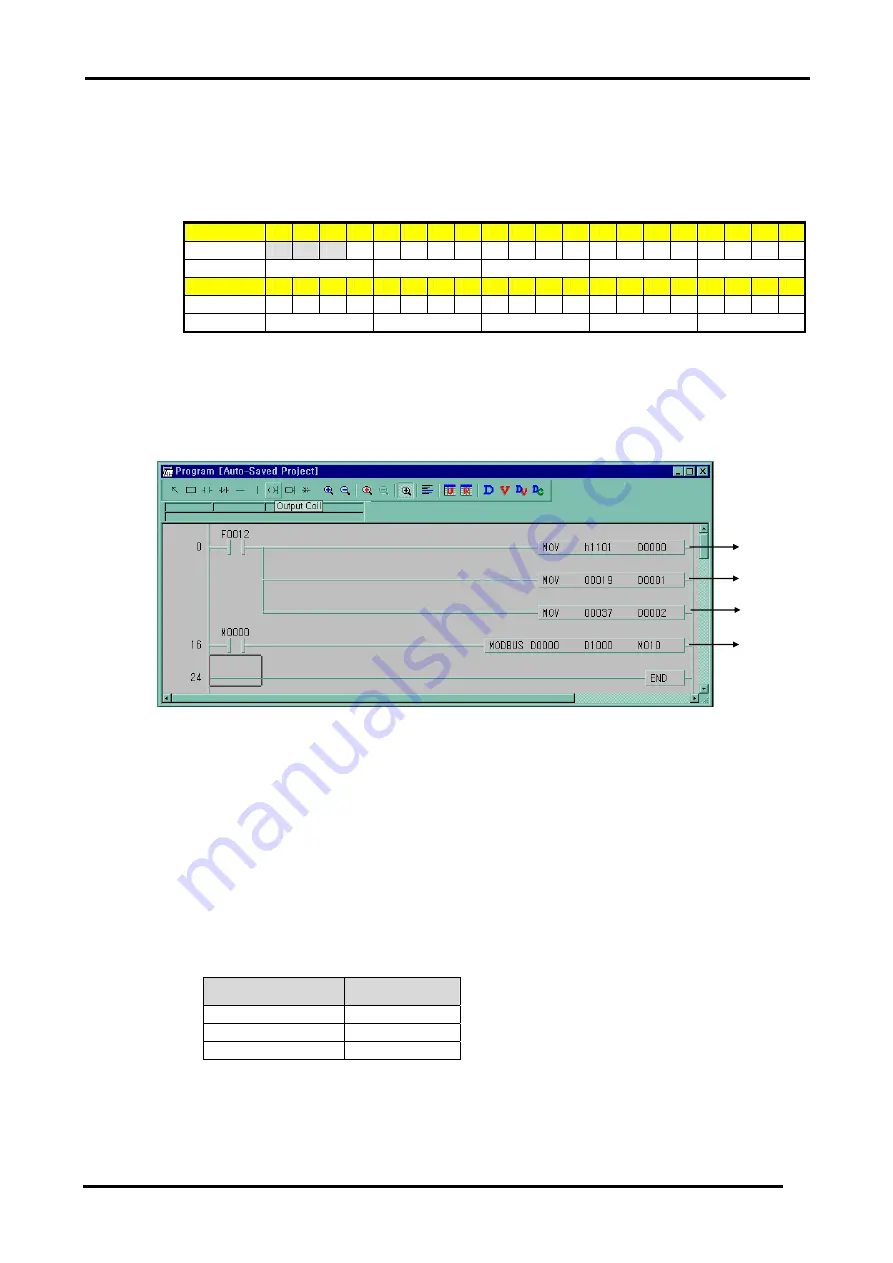
An example of sending the above data is as the following example 1.
Example 1) CD B2 0E 1B
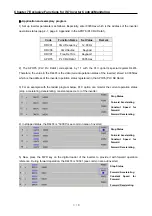
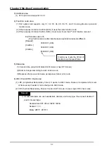
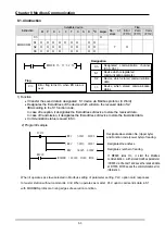
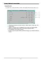
It designates slave station and function code (No. of station : h11(17) , function code : h01)
①
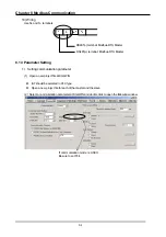
Address setting
②
- Address ‘0’ at MODBUS protocol means address ‘1’ actually .So if you want to designate
address ‘20’, write address ‘19’
Reading number setting (Reading number is 37 from 20 to 56.)
③
This is MODBUS Communication instruction.
④
채널
1
을
통해서
D000 ~ D002
까지
설정된
형식으로
통신하고
받는
데이터는
D1000
부터
저장
하는
설정입니다
.
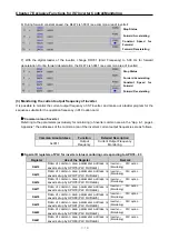
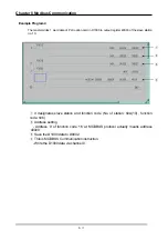
- Data is sent starting from the low bit by byte unit. If the deficient bit of a byte is filled with 0. An
example of sending the above data is as follows.
Example 1) CD 6B B2 0E 1B
Device
Stored data
D1000
h CD 6B
D1001
h B2 CE
D1002
h 00 1B
③
④
②
①


