Milling and drilling
28
ProtoMat M60
7.0 Milling and drilling
7.1 Securing the PCB on the machine bed
› Make 3.05 mm alignment holes in the base material and backing
material spaced the same distance as the alignment pins. This can
also be done with any upright drilling machine. Take into
consideration that the diameter decreases during galvanic through-
plating process so do not plate these holes.
› Move the mill/drill head to the PAUSE position. Insert alignment pins
in the front and rear two-pin strips but, even so, check that the front
two-pin strip is pushed forwards against the reference pin in the
machine groove.
› Position the pre-drilled base material and drilling base over the
alignment pins. The format of the base material should be selected in
a way that the two-pin slides do not have to be moved by more than
10 mm, as otherwise the two-pin system precision decreases.
› Now secure the base material in position with drafting tape (masking
tape is not recommended because it leaves a residue) on all sides.
This prevents the corners of the PCB turning upwards.
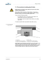
fig. 8: Securing the PCB
The alignment pins hold the PCB in position. This is essential particularly
for contour milling. They are also the reference when turning double-
sided PCBs.
Caution! Switch on the vacuum system! Take into consideration
that the vacuum filter might need to be changed! It is important that
there is no dirt (adhesive tape remains, drilling or milling chips)
between the individual layers so that the base material can be laid
absolutely flat. Small particles under the base material would
adversely affect milling depth uniformity.
1
- Machine bed (aluminum base plate)
4
- Drilling base, 2 mm thick
2
- Alignment pins, 3 mm in diameter
5
- Drafting tape
3
-Base material, approx. 1.6 mm thick
6
- Two-pin strip


