background image

However, the alarm remains active in the alarm listing until the
reason for the alarm has been removed.

Disable

Disables the current alarm setting. The alarm does not show
again unless you turn it back on in the Alarms dialog.

There is no time-out on the alarm message or siren. They remain
until you acknowledge the alarm or until the reason for the alarm is
removed.

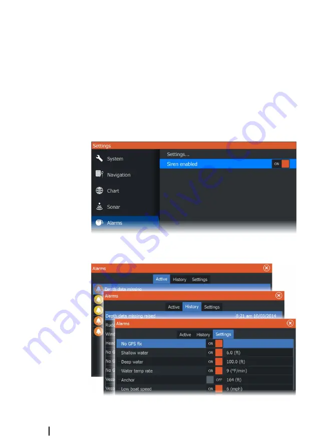
Alarms dialog

Enable the alarm siren from the Alarms dialog.

Select the settings option to open the Alarms Settings dialog. All
alarms are setup in the Alarms Settings dialog. 

74

Alarms

 | Hook² Series Operator Manual

Summary of Contents for 12 TS

Page 1: ...ENGLISH Hook2Series OperatorManual 5HDI 5TS 7XGPSTS 7HDI 7TS 9TS 9HDI and12TS www lowrance com...

Page 2: ......

Page 3: ...anuals user guides and other information relating to the product Documentation may be translated to or has been translated from another language Translation In the event of any conflict between any Tr...

Page 4: ...mpatibility standard 2008 The relevant Declaration of Conformity is available in the product s section at the following website www lowrance com About this manual This manual is a reference guide for...

Page 5: ...ized as follows Note Used to draw the reader s attention to a comment or some important information Warning Used when it is necessary to warn personnel that they should proceed carefully to prevent ri...

Page 6: ...6 Preface Hook Series Operator Manual...

Page 7: ...izing the Home page wallpaper 19 Data Overlay 20 Adding new custom pages 21 Edit or delete custom pages 21 Adjusting the split on multiple panel pages 23 Charts 23 The Chart panel 24 Selecting chart t...

Page 8: ...to cursor position 46 Navigate to a waypoint 46 Navigate a route 47 Navigation settings 49 Sonar 49 The Sonar image 50 Zooming the image 50 Viewing history 50 Customize the image settings 50 Custom an...

Page 9: ...ing Structure overlay 71 StructureMap tips 71 Recording StructureScan data 71 Using StructureMap with mapping cards 72 Structure options 73 Alarms 73 Alarm system 73 Type of messages 73 Alarm messages...

Page 10: ...85 Simulator 85 Demo mode 85 Simulator source files 86 Advanced simulator settings 10 Contents Hook Series Operator Manual...

Page 11: ...us and dialogs press to highlight an option 4 Exit X On a maximized multiple panel page press to return to the multiple panel page In menus and dialogs press to return to previous menu level and to ex...

Page 12: ...e page The Home page is accessed from any operation by a short press on the Pages key Note Page icons on the Home page vary with model type 1 2 3 1 Tools panel Select a button to access dialogs used f...

Page 13: ...or system faults occur Each application connected to the system is presented on panels The application can be presented as a full page or in combination with other panels in a multiple panel page All...

Page 14: ...range border Maximize the active panel by pressing the Menu Enter key Press the Exit X key to go back to the multiple panel page To display the panel menu it must first be maximized Once maximized pre...

Page 15: ...ions that toggle on and off an orange bar across the top of the icon indicates the function is activated as shown in the Data overlay icon above Turning the system on and off You turn the system on an...

Page 16: ...ing Use the stop sonar option anytime you want to disable all sonar but not power off the unit Using menus and dialogs Menus The menu is used to operate the system and to adjust settings Press the Men...

Page 17: ...th and temperature at the cursor To remove the cursor and cursor elements from the panel press the Cursor Waypoint key Creating a Man Overboard waypoint If an emergency situation should occur you can...

Page 18: ...enu and select the Info option in the menu The MOB waypoint menu option When an MOB waypoint is activated you can use the Waypoint MOB menu option to Move it on the panel Edit its attributes Delete it...

Page 19: ...at can be seen in the files browser When a picture is chosen as the wallpaper it is automatically copied to the Wallpaper folder Data Overlay You can have data information as overlay on a page Turning...

Page 20: ...he page editor dialog 2 Use the Arrow keys to highlight a panel then press the Menu Enter key The panel is added to the page 3 Optional Repeat step 2 to add additional panels A maximum of 4 panels are...

Page 21: ...2 Use the Arrow keys to Select the X option on a custom page icon and press the Menu Enter key to remove the page Select the tool option on a custom page icon and press the Menu Enter key to display t...

Page 22: ...4 Use the Arrow keys to move the split to the desired position 5 Press the Menu Enter key to save the split adjustment 22 Customizing your system Hook Series Operator Manual...

Page 23: ...on relative to land and other chart objects On the chart panel you can plan and navigate routes and place waypoints You can overlay a StructureScan image Refer to StructureMap on page 70 The Chart pan...

Page 24: ...vessel symbol includes a question mark Chart scale You zoom in and out on the chart by using the Zoom keys Chart range scale and range rings interval when turned on are shown in the lower right corne...

Page 25: ...ute basic information for the selected item is displayed as a pop up Note Pop up information has to be enabled in chart settings to see basic item information Select the info option in the menu to dis...

Page 26: ...chart panel Chart orientation You can specify how the chart is rotated in the panel The chart orientation symbol in the panel s upper right corner indicates the north direction Northup Courseup North...

Page 27: ...nded to be sufficient for safe navigation Depth palette Controls the Depth palette used on the map Depth filter Filters out depth values shallower than the selected depth filter limit Safety depth C M...

Page 28: ...ailable if you do not have the appropriate Navionics charts or chart card inserted For more information on what is required for these features refer to www navionics com You can also get a message if...

Page 29: ...elect SonarChart Live overlay the menu expands to display SonarChart Live Options Use the options to set the transparency and minimum depth Transparency The SonarChart Live overlay is drawn on top of...

Page 30: ...min value of the evaluated day The red arrow is used when tide is rising and the blue arrow is used when tide is falling Note All numeric values are shown in the relevant system units unit of measure...

Page 31: ...is rounded to the nearest available contour line NoDepthhighlightrange Depthhighlightrange 6m 12m Shallow water highlight Highlights areas of shallow water This allows you to highlight areas of water...

Page 32: ...to 20 m after which it is all white Chart details Provides you with different levels of geographical layer information Chart settings Select the settings option in the System Controls dialog to acces...

Page 33: ...ms on panels Course extension line Turns on off displaying the Course Over Ground COG extension line on the panel The COG is based on information from the GPS Extension line length When the course ext...

Page 34: ...our vessel s trail and place waypoints GPS plotter page 1 2 3 6 4 5 1 Data overlay Can be edited moved or removed Refer to DataOverlay on page 19 2 Waypoint 3 Vessel with trail displaying the trail is...

Page 35: ...e edge of the panel in the desired direction To remove the cursor and cursor elements from the page press the Cursor Waypoint key This also centers the image to the vessel position GPS view options GP...

Page 36: ...ally traveling COG is oriented up Look ahead Moves the vessel icon on the panel to maximize your view ahead of the vessel Waypoints Routes and Trails You can position and manage waypoints routes and t...

Page 37: ...m to suit the panel scale Grid lines Turns on off viewing of longitude and latitude grid lines on the panel Waypoints Routes Trails Turns on off displaying these items on panels Course extension line...

Page 38: ...e dialogs are accessed from the Tools panel on the Home page Select the menu icon on the dialog to access additional options Waypointoptions Routesoptions Trailsoptions Waypoints A waypoint is a user...

Page 39: ...waypoint in the menu The menu expands to include the move option 4 Select the move option in the menu 5 Use the Arrow keys to move the waypoint to the new position 6 Press the Menu Enter key The wayp...

Page 40: ...name is displayed Creating a new route on the page 1 Select the new route option from the menu 2 Press the Cursor Waypoint key to activate the cursor on the panel 3 Use the Arrow keys to position the...

Page 41: ...to use and press the Menu Enter key 4 Follow the prompts to make changes and save your changes Delete a route You can delete a route by placing the cursor over the route and then selecting the route...

Page 42: ...Enter key Converting Trails to Routes You can convert a trail to a route from the Edit Trail dialog The dialog is accessed by selecting the Trails tab in the dialog displayed when you select Waypoint...

Page 43: ...the dialog displayed when you select the Waypoint Routes and Trails tool on the Home page Select the name field to change the name Turn on Display to show the route on the panel Trails Trails are a gr...

Page 44: ...ails tool on the Home page and selecting the Trails tab Trails settings Trails are made up of a series of points connected by line segments whose length depends on the frequency of the recording You c...

Page 45: ...You can color trails by selecting the trail in the Trails dialog and set the color in the Edit Trail dialog Waypoints Routes and Trails Hook Series Operator Manual 45...

Page 46: ...osition the cursor at the selected destination on the panel and then select the Goto Cursor option in the menu Note The Goto Cursor menu option is not available if you are already navigating Navigate...

Page 47: ...vessel goes beyond this limit an alarm is activated XTE alarm Cross track error Turns on off the XTE alarm Trails Opens the Trails dialog where trails settings can be adjusted and trails can be conve...

Page 48: ...ialog Auto the unit positions a point automatically when a course change is registered Distance select the Distance field and enter the distance you want to record Time select the Time field and enter...

Page 49: ...detect fish and examine the structure of the bottom The Sonar image 4 3 2 5 7 1 6 1 Fish arches 2 Speed over ground 3 Depth 4 Water Temperature 5 Frequency 6 Bottom 7 Range scale Optional Sonar data...

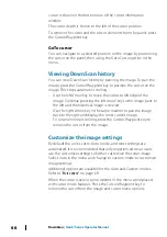
Page 50: ...historical image is viewed Use the right Arrow key in the same manner to pan the image back to the right and display the most current image To resume normal scrolling press the Cursor Waypoint key to...

Page 51: ...w Note Auto Sensitivity is the preferred mode for most conditions Auto sensitivity Auto sensitivity automatically adjusts the sonar return to the optimal levels Auto sensitivity can be adjusted to you...

Page 52: ...engine vibration and air bubbles can clutter the image The noise rejection option filters the signal interference and reduces the on screen clutter Surface clarity Wave action boat wakes and temperatu...

Page 53: ...ght side of the display shows the range that is magnified If you increase the zooming factor the range is reduced You see this as reduced distance between the zoom bars Bottom lock The bottom lock mod...

Page 54: ...ty Palettes You can select between several display palettes optimized for a variety of fishing conditions Fish ID You can select how you want the echoes to appear on the screen You can also select if...

Page 55: ...ints and the distance listed in the Cursor Information window 4 Continue selecting new measuring points if required You can use the menu to re position the start point and the end point as long as the...

Page 56: ...or to a memory card in the card reader Create StructureMap Note This option is only available on models that have TripleShot StructureScan capability If your model has TripleShot StructureScan capabi...

Page 57: ...p in the Logging Sonar dialog Select Convert to create a smf file in the Log folder Refer to Files on page 78 Viewing the recorded sounder data Both internally and externally stored sounder records ma...

Page 58: ...ormal sonar image You exit the view function by pressing the Exit X key Depth offset All transducers measure water depth from the transducer to the bottom As a result water depth readings do not accou...

Page 59: ...ould be set as a positive value For example 0 5 m 1 77 ft For depth below transducer set the offset to 0 Water temperature calibration Temperature calibration is used to adjust the water temperature v...

Page 60: ...ctureScan image The view The StructureScan image can be set up to show left side right side or both left and right side scanning 1 Speed over ground 2 Depth 3 Temperature 4 Frequency 6 Range scale Zoo...

Page 61: ...cursor elements from the panel press the Cursor Waypoint key Viewing StructureScan history You can view StructureScan history by panning the image To pan the image press the Cursor Waypoint key to pos...

Page 62: ...When the cursor is active some options in the menu are replaced with cursor mode features Press the Cursor Waypoint key to remove the cursor from the image and cursor menu options Custom options Rang...

Page 63: ...ur settings Advanced StructureScan settings Surface clarity Wave action boat wakes and temperature inversions can cause on screen clutter near the surface The surface clarity option reduces surface cl...

Page 64: ...he cursor on the point from where you want to measure the distance 2 Start the measuring function from the More options menu option Note The measure function is not available in the menu unless the cu...

Page 65: ...ownScan image You can zoom a DownScan image by using the Zoom keys Using the cursor on the DownScan panel By default the cursor is not shown on the DownScan image To position the cursor on the image p...

Page 66: ...age pans to the left and the historical image is viewed Use the right Arrow key in the same manner to pan the image back to the right and display the most current image To resume normal scrolling pres...

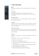
Page 67: ...with lower resolution Restore mode default This menu option is available if you customize one or more settings When selected all the customized settings are changed back to the default settings Contr...

Page 68: ...tance between the position of two observations on the image 1 Position the cursor on the point from where you want to measure the distance 2 Start the measuring function from the More options menu opt...

Page 69: ...the cursor from the image and the image resumes to normal scrolling DownScan Hook Series Operator Manual 69...

Page 70: ...ge The example below shows a chart panel with Structure overlay combined with a traditional SideScan panel You move around in the chart as usual when you have a Structure overlay Use the Zoom keys to...

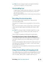
Page 71: ...ncludes information about file size Keep the size of your logs to 100MB or less to allow for faster file conversion The recording is stopped by re selecting the record function Converting StructureSca...

Page 72: ...y Sets the opaqueness of the Structure overlay With minimum transparency settings the chart details are almost hidden by the StructureMap overlay Palette Selects Structure palette Contrast Determines...

Page 73: ...are classified according to how the reported situation affects your vessel The following color codes are used Color Importance Red Critical Orange Important Yellow Standard Blue Warning Green Light w...

Page 74: ...urn it back on in the Alarms dialog There is no time out on the alarm message or siren They remain until you acknowledge the alarm or until the reason for the alarm is removed Alarms dialog Enable the...

Page 75: ...Provides access to application and system settings System settings The system settings provides access to the following Language Controls the language used on this unit for panels menus and dialogs C...

Page 76: ...ude coordinates displayed on the panel Magnetic variation Magnetic variation is the difference between true bearings and magnetic bearings caused by different locations of the Geographic and the Magne...

Page 77: ...e Charts are not available on 7x TS models Provides options and dialogs where you specify settings for your charts Settings and display options made in the Chart settings page are common for all chart...

Page 78: ...from the Tide station field To change the date use the Arrow keys to access the date field and press the Menu Enter key to access the calendar function Trip Provides trip information Use to reset trip...

Page 79: ...to a card Exporting files is covered in the section Maintenance on page 80 Tools Hook Series Operator Manual 79...
Page 80: ...irt etc can scratch the protective coating if using a damp cloth Use a light fresh water spray then wipe the unit dry with a micro fiber or a soft cotton cloth Do not apply pressure with the cloth To...

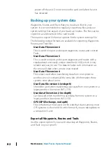
Page 81: ...t device or PC connected to the internet Software upgrades The latest software is available for download from our website www lowrance com Before initiating an update to the unit itself be sure to bac...

Page 82: ...e identifier UUID which is very reliable and easy to use The data includes such information as the time and date when a route was created User Data File version 4 This is best used when transferring d...

Page 83: ...the other boundary box corner 6 Press the Exit X key to indicate that the box covers the region you want to export The Export Region dialog opens 7 Select the export option 8 Select the appropriate f...

Page 84: ...ng the backed up files in the unit s card reader 2 Open the Files dialog from the tool panel and select the memory card 3 Browse to the file you want to import and select it This opens the details dia...

Page 85: ...he product it changes pages automatically adjusts settings opens menus etc Note Demo mode is designed for retail showroom demonstrations Simulator source files You can select which sonar data files ar...

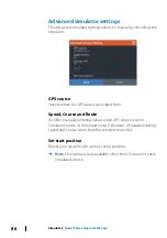
Page 86: ...nd Route Used for manually entering values when GPS source is set to Simulated course or Simulated route Otherwise GPS data including speed and course come from the selected source file Set start posi...

Page 87: ...ionics chart options 29 North up 26 Overlay 26 Panning 24 Positioning the vessel on the chart panel 26 Selecting chart type 24 Settings 32 Zooming 24 Colorline Sonar 52 Configuring overlay data 20 Con...

Page 88: ...tic variation 76 Man Overboard Cancel navigation to MOB 18 Creating a MOB 17 Display information 18 Manual About 4 Version 5 Measuring distance 55 64 68 Multiple panel custom pages 14 Multiple panel p...

Page 89: ...Simulator 85 Demo mode 85 Source files 85 SL2 format 56 SLG format 56 Software upgrade 81 Software version 5 Software How to update 81 Sonar 49 Auto mode 50 Auto sensitivity 51 Colorline 52 Customize...

Page 90: ...ize 75 Time 76 Tools 75 Tools Routs 78 Settings 75 Trails 78 Waypoints 78 Trails Converting trails to routes 42 Creating new 44 Dialog 38 Navigating settings 47 Settings 44 Turning the unit on and off...

Page 91: ...Z Zoom Sonar 53...

Page 92: ...988 11760 001...

Reviews:

Related manuals for 12 TS