Maximum Output Power per Carrier
5-10
InterReach Fusion SingleStar Installation, Operation, and Reference Manual
CONFIDENTIAL
D-620605-0-20 Rev A
900 MHz Paging/SMR
Designing for Capacity Growth
Fusion SingleStar systems are deployed to enhance in-building coverage and/or to
off-load capacity from a macro cell site. In many instances, subscriber usage
increases with time and the wireless provider responds by increasing the load on the
installed Fusion SingleStar system. For example, the initial deployment might only
require two RF carriers, but four RF carriers may be needed in the future based on
capacity growth forecasts. There are two options for dealing with this scenario:
1.
Design the initial coverage with a maximum power per carrier for four RF carri-
ers. This will likely result in additional RAUs.
2.
Design the initial coverage for two RF carriers, but reserve RAU ports on the Hub
for future use. These ports can be used to fill potential coverage holes once the
power per carrier is lowered to accommodate the two additional carriers.
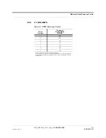
Table 5-6
Paging/SMR Power per Carrier
No. of
Carriers
Power per Carrier (dBm)
iDEN
Analog
FM
CQPSK
C4FM
Mobitex
POCSAG/
REFLEX
1
17.5
26.0
22.0
26.0
26.0
26.0
2
14.0
19.5
17.0
19.5
19.5
19.5
3
11.5
16.5
14.5
16.0
16.0
16.0
4
10.0
13.5
12.5
13.5
13.5
13.5
5
9.0
12.0
11.0
11.5
6
8.0
10.5
9.5
10.0
7
7.0
9.5
9.0
9.0
8
6.5
8.5
8.0
8.5
9
6.0
8.0
7.5
7.5
10
5.5
7.0
7.0
7.0
Note: Operation at or above these output power levels may prevent Fusion SingleStar from meeting RF performance specifications or FCC Part 15 and
EN55022 emissions requirements. Refer to the Fusion SingleStar Installation, Operation, and Reference manual for system design information.

