LG LSE3092ST, Service Manual
The LG LSE3092ST Owner's Manual is a comprehensive guide for mastering the features and functionalities of this high-performing appliance. Easily download the manual for free from manualshive.com and unleash the full potential of your LG LSE3092ST with step-by-step instructions and expert tips.
Share
Download


Reviews:
No comments
Related manuals for LSE3092ST

RGB790DETBB
Brand: GE Pages: 56

TTW-330
Brand: TECHWOOD Pages: 13

performa
Brand: Maytag Pages: 52

CRDSCD230-5B
Brand: Brigade Pages: 14

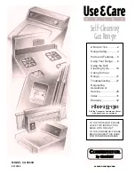
Drop-In Ceramic Electric Range
Brand: Whirlpool Pages: 8

CEL1110AAH
Brand: Whirlpool Pages: 15

Acros ACE3411KA2
Brand: Whirlpool Pages: 13

AGR5630BD
Brand: Whirlpool Pages: 20

ACE2200
Brand: Whirlpool Pages: 15

ADN 614
Brand: Whirlpool Pages: 20

Admiral mf12120
Brand: Whirlpool Pages: 20

9763000
Brand: Whirlpool Pages: 16

ADN 020/WP
Brand: Whirlpool Pages: 23
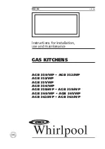
AGB 350/WP
Brand: Whirlpool Pages: 22

9762362A
Brand: Whirlpool Pages: 20

9762358A
Brand: Whirlpool Pages: 20

9762363A
Brand: Whirlpool Pages: 20
CGS365H
Brand: Whirlpool Pages: 32


