117
8. TROUBLESHOOTING
Symptom
Cause
Action
Compressor is not
operating.
Wire opened
Control fuse opened
High pressure switch(HPS) stopped
Loosely connected terminal
Inaccurately connected control unit
Check unconnected areas
Check control circuit's grounding or short circuit
status, replace fuse
Initialize present alarm using navigator
Check connection from CCP to contact point
Check wire and reconnect wire
Excessive lowering of voltage
Check wire voltage
Judge voltage lowering point and correct defect
Compressor motor defect
Check whether motor coil winding is open or
short-circuit
If needed, replace compressor
Compressor stop
Preliminary lubrication was not successful
Operate oil pump, Check oil pressure transducer,
Check oil solenoid valve movement
Compressor
stopped due to ab-
normally low pres-
sure.
Leakage
Defective transducer
Refrigerant insufficient
Broken expansion device
Wholly/partly clogged strainer
Repair leakage area and charge again
Replace transducer
Add refrigerant
If needed, repair/replace
Disengage strainer and clean
Compressor
stopped due to ab-
normally high pres-
sure.
High pressure switch abnormal operation
Compressor discharge valve partly closed
Condenser water piping clogged
Condenser scale problem occurred
Replace switch
If valve is open or defective, replace
Check piping. If defective, repair or replace
Clean condenser
Chiller operated ab-
normally for a long
time/continuously
Refrigerant amount-insufficient charging
Control fuse broken
Partly or completely clogged strainer
Defective insulation
Service load exceeding the designed ca-
pacity
Inefficient compressor
Add refrigerant
Replace control unit
Clean or replace
Replace or repair
Examine load condition
Check loader solenoid valve. If needed, replace
Abnormal noise
Pipe vibration
If needed, install supportive piping
Expansion valve noise
Add refrigeran
Check clogged piping strainer
Compressor noise
Replace compressor(worn out bearing)
Check for loosened compressor bolts for attach-
ing compressor to chiller.
Compressor oil
loss
Leakage from system
Mechanical damage in rotor
Find leakage and repair
Replace compressor
Abnormally high
temperature piping
Refrigerant insufficient due to leakage
Repair leakage area and charge again
Abnormally low
temperature piping
Stop valve partly closed or limited
Open valve or remove jam
Compressor loader
abnomally oper-
ated
Electronic valve coil defect
Loading solenoid valve defect
Wrongly wired solenoid valve
Replace coil
Replace valve
Connect wire again correctly
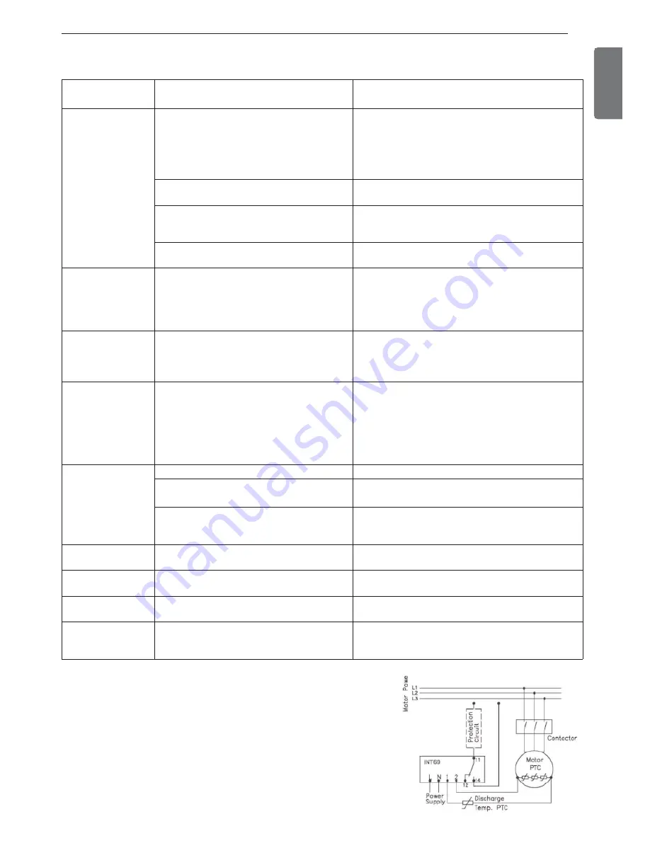
8-3. Actions for screw compressor status
To protect the compressor, 2 PTC temperature sensors are installed in
the compressor's discharge gas side and inside of motor coil. These
sensors are connected to INT69 control module to check motor coil
temperature and discharge gas temperature. In case one of the temper-
ature value is higher than the set response temperature of the PTC ther-
mistor, the sensor resistance increases, and the INT69 control module
blocks the motor contactor. The interrupting temperature of the motor
coil winding is 120℃ and the restarting temperature is 75℃. The interrupt-
ing temperature of the compressor discharge protection is 110℃ and the
restarting temperature is 60℃. The problem resolving method of the
compressor is described in the table above.
Summary of Contents for LCWW
Page 119: ......


