background image

4-36

Lexmark™ E360d, E360dn

4513-420, -430


6.

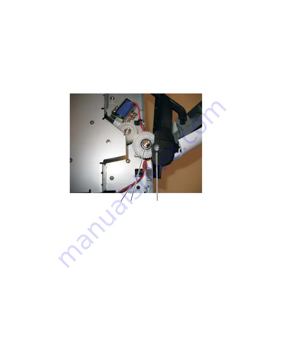
Lift and remove the left door mount (C) away from the side frame, and unroute the cable (D) with a spring 
hook.

7.

Reinstall the left door mount, and place the printer on it’s top. 

Note:  

Be careful to not mar the finish of the printer.

8.

Disconnect the cable (D) from J25 on the controller board.

Installation note: 

Install the two screws holding the new solenoid in place, and route the cable (D) behind the MPF clutch 
(E).

After disconnecting the old solenoid cable, connect the new solenoid cable to J25 on the controller board. 

E

C

D

Summary of Contents for E360D series

Page 1: ...420 4513 430 Table of contents Start diagnostics Safety and notices Trademarks Index Lexmark and Lexmark with diamond design are trademarks of Lexmark International Inc registered in the United State...

Page 2: ...ves appropriate without incurring any obligation to you References in this publication to products programs or services do not imply that the manufacturer intends to make these available in all countr...

Page 3: ...el and menus 2 2 Indicator light 2 2 Buttons 2 3 Diagram of the printer menus 2 5 Messages and error codes 2 6 User attendance messages 2 6 Cartridge error messages 2 9 Paper jam error codes 200 serie...

Page 4: ...3 12 EP setup 3 13 Event log 3 14 Exit Diagnostics 3 15 Printhead assembly electronic adjustment 3 16 Printhead assembly mechanical adjustment 3 17 Repair information 4 1 Handling ESD sensitive parts...

Page 5: ...sensor removal 4 60 Top cover assembly removal 4 61 Transfer roll removal 4 63 Upper front guide assembly removal 4 64 Wear strip tray 1 and 250 sheet tray 2 removal 4 65 Wear strip 550 sheet tray 2...

Page 6: ...vi Lexmark E360d E360dn 4513 420 430...

Page 7: ...oder bei ordnungsgem er Wartung durch den Kundendienst Laserbestrahlung die Klasse I bersteigen w rde Menschen keinesfalls erreicht Avis relatif l utilisation de laser Pour les Etats Unis cette impri...

Page 8: ...o de pot ssio de 7 milliwatts operando numa faixa de comprimento de onda entre 655 e 675 nan metros O sistema e a impressora laser foram concebidos de forma a nunca existir qualquer possiblidade de ac...

Page 9: ...ettaessa olet alttiina n kym tt m lle lasers teilylle l katso s teeseen VARNING Osynlig laserstr lning n r denna del r ppnad och sp rren r urkopplad Betrakta ej str len Laser notis Denna skrivare r i...

Page 10: ...IEC 60825 1 Els productes l ser de classe I no es consideren perillosos Aquesta impressora cont un l ser de classe IIIb 3b d arseni r de gal li nominalment de 7 mil liwats i funciona a la regi de lon...

Page 11: ...Notices and safety information xi 4513 420 430...

Page 12: ...xii Lexmark E360d E360dn 4513 420 430...

Page 13: ...indique la pr sence d une tension dangereuse dans la partie du produit sur laquelle vous travaillez D branchez le produit avant de commencer ou faites preuve de vigilance si l ex cution de la t che ex...

Page 14: ...precauciones necesarias PRECAUCI N este s mbolo indica que el voltaje de la parte del equipo con la que est trabajando es peligroso Antes de empezar desenchufe el equipo o tenga cuidado si para trabaj...

Page 15: ...producte est orientada exclusivament a professionals i no est destinada a ning que no ho sigui El risc de xoc el ctric i de danys personals pot augmentar durant el proc s de desmuntatge i de servei d...

Page 16: ...ling FRUs 5 Connector locations uses illustrations to identify the connector locations and test points on the printer 6 Preventive maintenance contains the lubrication specifications and recommendatio...

Page 17: ...information on E460dn and E460dw see the 4513 630 63W 6EW service manual Maintenance approach The diagnostic information in this manual leads to the correct field replaceable unit FRU or part Use the...

Page 18: ...verview of the operator panel The operator panel consists of these items A 2 line liquid crystal display LCD that shows text Six buttons Menus Back Navigation with Left Menu Select and Right Menu and...

Page 19: ...al font cards DBCS Option slots Memory slots 1 1 Flash memory option card 2 2 Only one slot is active for 64MB flash memory or font card Item 4513 420 Lexmark E360d 4513 430 Lexmark E360dn Print resol...

Page 20: ...Compatibility Windows Macintosh Linux Windows Macintosh Linux Standard local connections Parallel USB Standard network connections Ethernet 10 100 Base Tx x Wireless ethernet 802 11b g n x x Optional...

Page 21: ...ual integrated print duplex Integrated Integrated Envelope conditioning x x Available output trays Standard 150 sheet sensing bin Toner and photoconductor Toner cartridge 2 300 standard pages SWE 3 50...

Page 22: ...transparency recycled labels bond letterhead preprinted colored paper light paper heavy paper rough cotton custom type x 60 163 g m 16 43 lb 50 paper 15 labels 10 transparencies Card stock 120 163 g...

Page 23: ...al feed sensor B C 9 0 C Upper end feed rolls C D 59 8 D Input sensor D E 44 9 E Transfer roll E F 112 7 F Fuser F G 21 4 G Fuser exit rolls G H 114 8 H Fuser exit sensor H I 7 5 I Exit rolls I J 17 0...

Page 24: ...dicators on the 250 sheet tray before pushing the tray into the printer Make sure paper guides are positioned before loading the paper or specialty media Do not remove trays while a job is printing Be...

Page 25: ...d Replaceable Unit HBP Host Based Printing HVPS High Voltage Power Supply LCD Liquid Crystal Diode LED Light Emitting Diode LSU Laser Scanning Unit LVPS Low Voltage Power Supply NVRAM Nonvolatile Rand...

Page 26: ...1 10 Lexmark E360d E360dn 4513 420 430...

Page 27: ...and E360dn have an operator panel with messages See Overview of the operator panel and menus on page 2 2 Power On Self Test POST sequence The following is an example of the events that occur during t...

Page 28: ...tor light The indicator light gives information about the status of the printer If the light is The printer is Off Off On On but idle Blinking On and busy Menu button LCD display Indicator light Back...

Page 29: ...s and release or to scroll through menus menu items or printer options or to move between screens and menu options These buttons can also be used to automatically increase or decrease the desired numb...

Page 30: ...pplies Warnings status This is where printer status supplies messages and show me screens are viewed Indicator light The indicator light indicates printer status If the light is off then the printer p...

Page 31: ...e Border Job Menu Reset Printer Utilities Menu Quick Demo Print Menus Print Stats Print Net Setup Print Fonts Print Demo Factory Defaults Hex Trace Quality Menu Print Resolution Toner Darkness Small F...

Page 32: ...ssage to clear Disabling Menus Wait for the message to clear Note The printer settings cannot be changed from the control panel while the menus are disabled Enabling Menus Wait for the message to clea...

Page 33: ...the Ready message Printing Directory List The printer is processing or printing a directory of all files stored in flash memory Wait for the message to clear Printing Font List The printer is process...

Page 34: ...ull error Res Reduced remains on the display while the job prints Restoring Factory Defaults Wait for the message to clear Note When factory default settings are restored All downloaded resources font...

Page 35: ...ough time elapsed since the printhead started to expect the printhead mirror motor lock Possible causes include bouncy sensor or exceptionally fast pick perhaps due to media pre staged in the source t...

Page 36: ...l is designed to handle Probable causes ESD or noise on hsync signal 200 30 Narrow media sensor covered during warm up 200 32 Media more than 14 inches too long over the manual feeder sensor Possible...

Page 37: ...duplex 232 02 Page in duplex ahead of current reversing page never staged 233 00 Duplex jam while picking from the device 233 01 Page in duplex never picked 233 02 Feed error picking from the duplex 2...

Page 38: ...feed from tray 2 Pages in the paper path have been flushed to the output bin 251 00 Paper jam near the manual feeder 251 10 Second pick attempt failed from manual feeder 251 11 Failed to feed from ma...

Page 39: ...r too cool when heating to desired temperature after slope change 920 05 Fuser under temperature while printing 920 06 Fuser under temperature while printing 920 07 Fuser under temperature while print...

Page 40: ...ror 925 02 Too hot to do lamp detection and NVRAM bit indicates previous wrong lamp detected Fan service errors 927 00 Service fan error 927 03 Main fan took too long to ramp up 927 04 Main fan is und...

Page 41: ...Printhead sweep error detected resonant frequency out of expected range 935 26 Printhead sweep error timed out waiting for end of sweep Transport motor service errors 936 01 No lock detected at norma...

Page 42: ...e Cover interlock switch service check on page 2 19 POST completes but the LCD does not come on See Operator panel service check on page 2 23 Main motor does not come on See Main motor service check o...

Page 43: ...See Operator panel service check on page 2 23 Operator panel lights are off or very dim See Operator panel service check on page 2 23 Blank page See Blank page on page 2 26 Black page See Black page...

Page 44: ...power up without a functioning operator panel 4 The controller board assembly The LED adjacent to J12 will be illuminated if the card is powered and good 5 The operator panel See Operator panel servic...

Page 45: ...troller board assembly should apply 24 V dc to pin 2 If voltage is not present then check or replace the controller board See Controller board removal on page 4 6 If voltage is present then check pin...

Page 46: ...replace the LVPS HVPS If not open then check the switch continuity across its conductors with the switch on Turn the switch off Plug the AC line into the LVPS HVPS and switch unit on Note Voltages ar...

Page 47: ...ecessary If the cable tests good then replace the fuser Reconnect the cables turn the printer on and at 12 check for approximately 5 V dc on pin 1 and ground on pin 2 If line voltage is incorrect on p...

Page 48: ...the printer and check for the following voltages at J17 Verify ground at pin 5 for both the card and cable If these voltages are correct then check the main motor cable for continuity Remove the left...

Page 49: ...operator panel If any are incorrect then see Controller board service check on page 2 18 Buttons If the buttons do not respond then replace the operator panel There is no test or repair for the fault...

Page 50: ...CM assembly for signs of wear or damage Replace the tires as necessary ACM clutch Manual feed clutch Media feed clutch ASM tray 1 only Manual feed clutch solenoid Open left cover and observe the solen...

Page 51: ...the printer still fails to print on command from the host computer then replace the controller board 5 Check the USB cable for continuity FRU Action Fuser This problem is most likely due to a worn ba...

Page 52: ...ss To exit configuration turn the printer off Note Refer to the print defects guide at the end of the manual for repeating defects Blank page FRU Action Toner cartridge not a FRU Remove the toner cart...

Page 53: ...s 1 3 5 13 and 15 Verify ground on pins 10 12 14 16 and 18 If any of the values are incorrect then replace LVPS HVPS board If the grounds are incorrect then check ground paths Check continuity in the...

Page 54: ...or drum Try a new PC Kit Transfer roll Note Do not touch the transfer roll except at its ends Place a sheet of paper over the roll to prevent damage from finger oils or hand lotion Check the springs i...

Page 55: ...riation in the speed of the media as it feeds through the printer especially in the developer and transfer process It may also be a result of overly dry or moist environments With the printer off chec...

Page 56: ...cked With the printer off clear the path or clean the lens The toner cartridge or fuser may be defective Try a different toner cartridge Inspect the fuser at its entry for debris Toner smudges appear...

Page 57: ...ute the toner Replace the toner cartridge Solid black areas on transparencies There is a mismatch in the transparency and what the software is expecting Choose a different fill pattern in the software...

Page 58: ...The friction between sheets is too high Remove the media from Tray 1 or Tray 2 and fan it Don t overfill Tray 1 or the optional Tray 2 see media capacities in the media types and sizes chart in the U...

Page 59: ...urn the printer off Disconnect the printhead cables from J8 and J100 on the controller board Turn the printer on with the front door closed On the controller board verify 5 V dc on pin 10 at J8 and 5...

Page 60: ...2 34 Lexmark E360d E360dn 4513 420 430...

Page 61: ...ming Self Test displays 5 The message CONFIG MENU displays on the top line of the operator panel The Configuration menu group contains a set of menus settings and operations which are infrequently req...

Page 62: ...ns of the printer Reset PC Cnt See Reset photoconductor maintenance counter Reset PC Cnt on page 3 3 Prt Quality Pgs See Print quality pages Prt Quality Pgs on page 3 3 Reports Menu Settings Page Even...

Page 63: ...If the duplex is turned on then the pages are duplexed The Print Quality Test pages are printed in English and must always be printed on letter legal or A4 paper Reports The Reports menu contains two...

Page 64: ...lowing settings are not changed Display language Settings in the NETWORK PORTS MENU group Energy Conserve This menu controls what values appear on the Power Saver menu If Off is selected in the Energy...

Page 65: ...and options of the printer Registration See Registration on page 3 6 Print tests See Print tests on page 3 7 Hardware tests See Hardware tests on page 3 8 Duplex tests if installed See Duplex tests on...

Page 66: ...ther up or down on the physical page In order to preserve the bottom margin changing the top margin does not compress or expand the image Bottom Margin This setting moves the black plane s bottom marg...

Page 67: ...l Feeder MP Feeder Press or to scroll through the PRINT TESTS menu and then press to select the desired input source Single or Continuous is displayed on the screen A Single test feeds one sheet of me...

Page 68: ...s count field by one If the final Press count does not match the total number of buttons that are pressed then one or more buttons are malfunctioning Press to return to the HARDWARE TESTS menu screen...

Page 69: ...1 Select Quick Test from the DUPLEX TESTS menu 2 Select Single or Continuous by pressing or 3 Press to print the page Top Margin 1 Select Top Margin from the DUPLEX TESTS menu 2 To change the margin...

Page 70: ...oor during the feed test Note The upper front door cannot be opened during the feed test The feed test can be performed by using media from any if the installed input sources All pages used during thi...

Page 71: ...ing sensors are available in each output bin Press to select this test from the Output bin tests menu and then press again to select the desired output bin Closed will display on the operator panel if...

Page 72: ...al the values of the Picked Sides meter After all print tests have been completed the value will reset to 0 Note The value of this setting cannot be changed manually Press to exit the Page Count setti...

Page 73: ...ges of the page This feature does not work in PPDS emulation Par S Strobe Adj parallel strobe adjustment This setting adjusts the factory setting for the amount of time the strobe is sampled to determ...

Page 74: ...oint s darkness target Modifies the EP mechanism as necessary to adjust toner darkness No messages are displayed on the operator panel to give any indication that this test is running When deactivated...

Page 75: ...n clear error logs the contents of this log may not match the contents when you view the error log To print the error log 1 Press to enter Print Log from the EVENT LOG menu 2 Press Back to exit the EV...

Page 76: ...enter graph of the margin page Add that value to the current right margin setting printed on the left hand side of the margin page The right margin setting will also appear on the operator panel displ...

Page 77: ...appear skewed while the vertical lines remain parallel to the vertical edges There are no adjustments for skew Check the pick roll paper pick assembly for wear the paper path for obstructions the fuse...

Page 78: ...k See the left side of the figure below If the grid lines of the left flap align below the corresponding lines of the right side then adjust the printhead counterclockwise See the right side of the fi...

Page 79: ...y in your body to the printer Hold the ESD sensitive part by its edge connector shroud cover do not touch its pins If a pluggable module is being removed then use the correct tool Do not place the ESD...

Page 80: ...cted from light while out of the printer We recommend disconnecting all external cables from the printer to prevent damage during service Unless otherwise stated reinstall the parts in reverse order o...

Page 81: ...r just far enough to pull out the ACM pick tires Warning Open the duplex door only far enough to remove the ACM pick tires If the door is opened too far then it can become disengaged and interfere wit...

Page 82: ...b is gray then disconnect the old right and left tire hub assemblies from the ACM and replace with the new right and left tire hub assemblies If the left hub is black then remove the old right and lef...

Page 83: ...n 4 5 4513 420 430 Bezel removal 1 Open the front access door 2 Flex the top of the bezel and disconnect the latch A from the upper front cover 3 Disconnect the latches B from the upper front cover 4...

Page 84: ...the printer settings When either of these cards is new it obtains its settings from the other card Critical factory settings are lost when both cards are new and are replaced at the same time 1 Remove...

Page 85: ...elow the controller board The drip guard may need to be removed to access to the controller board 4 Remove the five screws C from the controller board 5 Lift the controller board and remove Note When...

Page 86: ...n sensor 1 Remove the right side cover See Right side cover assembly removal on page 4 58 2 Disconnect the cable A from the controller board 3 Use a 1 Phillips screwdriver to remove the screw B holdin...

Page 87: ...nt cover removal on page 4 25 3 Remove the left side cover See Left side cover removal on page 4 23 4 Remove the right side cover See Right side cover assembly removal on page 4 58 5 Disconnect the op...

Page 88: ...4 10 Lexmark E360d E360dn 4513 420 430 8 Disconnect the fuser link C 9 Remove the three screws D from the left side of the printer 10 Remove the door mounts C...

Page 89: ...ex removal 1 Remove the right side cover See Right side cover assembly removal on page 4 58 2 Remove the LVPS HVPS See LVPS HVPS removal on page 4 27 3 Remove the three screws A from the shield 4 Remo...

Page 90: ...4 12 Lexmark E360d E360dn 4513 420 430 5 Lift the duplex slightly push to the left and tilt to clear the right side of the printer 6 Remove the duplex...

Page 91: ...e removal 1 Remove the LVPS HVPS See LVPS HVPS removal on page 4 27 2 Remove the duplex See Duplex removal on page 4 11 3 Remove the main motor gear drive See Main motor gear drive removal on page 4 3...

Page 92: ...4 14 Lexmark E360d E360dn 4513 420 430 6 Remove the screw D from the gear E 7 Remove the plastic bushing F...

Page 93: ...Repair information 4 15 4513 420 430 8 Use a screwdriver to loosen the retainer clip G from the gear 9 Remove the gear H...

Page 94: ...0 Fan removal 1 Remove the right side cover See Right side cover assembly removal on page 4 58 2 Disconnect the cable A from the controller board and remove the two screws B holding the fan to the rig...

Page 95: ...on page 4 51 2 Remove the left side cover See Left side cover removal on page 4 23 3 Remove the upper front guide assembly See Upper front guide assembly removal on page 4 64 steps 1 3 4 Close the fro...

Page 96: ...4 18 Lexmark E360d E360dn 4513 420 430 6 Disconnect the MPF from the lower front cover 7 Disconnect the fuser link A from the front access door A...

Page 97: ...Repair information 4 19 4513 420 430 8 Disconnect the front access door cable B and pull it through the opening to clear the side frame 9 Disconnect the front access door from its hinges and remove B...

Page 98: ...val 1 Remove the rear exit guide See Rear exit guide assembly with sensor and reversing solenoid removal on page 4 56 2 Remove the two screws A 3 Partially pull the fuser forward for better access 4 P...

Page 99: ...Repair information 4 21 4513 420 430 5 Disconnect the AC cable C 6 Disconnect the thermistor cable D C B D...

Page 100: ...13 420 430 7 Disconnect the exit sensor cable E from the controller board 8 Remove the fuser Note Be careful to not damage the gears during the fuser installation Be sure to reinstall the AC cable dur...

Page 101: ...when removing the left side cover Make sure that the fuser cables are out of the way when removing the left side cover 1 Remove the paper tray 2 Remove the screw A from the rear left side of the print...

Page 102: ...E360d E360dn 4513 420 430 4 Swing the cover open and remove the left side cover Note There are two tabs on the top of the left side cover Do not swing the left side cover open too far or the tabs wil...

Page 103: ...low shows the E260d E260dn printer The lower front cover removal is the same for all models 3 Flex the lower front cover and disconnect it first from its right hinge and then from its left hinge Note...

Page 104: ...4 26 Lexmark E360d E360dn 4513 420 430 Installation note Use a flathead screw driver to press in on the door mount B while pulling on the front access door to connect the cover to the hinge C B C...

Page 105: ...cover removal on page 4 54 2 Remove the left side cover See Left side cover removal on page 4 23 3 Place the printer on its top with the rear facing you Note Be careful to not mar the finish of the pr...

Page 106: ...4 28 Lexmark E360d E360dn 4513 420 430 6 Remove the four screws C from the LVPS HVPS shield 7 Lift the LVPS HVPS and disconnect the three cables D C D...

Page 107: ...Repair information 4 29 4513 420 430 Note Squeeze the clip to remove the cables from their connectors E 8 Disconnect the transfer roll cable F 9 Lift and remove the LVPS HVPS E F...

Page 108: ...ove the left side cover See Left side cover removal on page 4 23 2 Disconnect the fuser link A from the front access door 3 Place the printer on its right side Note Be careful to not mar the finish of...

Page 109: ...Repair information 4 31 4513 420 430 5 Lift the gear drive and disconnect the main motor gear drive cable C 6 Remove the main motor gear drive...

Page 110: ...r removal on page 4 23 2 Open the front access door and disconnect the fuser link A 3 Place the printer on its right side Note Be careful to not mar the finish of the printer 4 Remove the four screws...

Page 111: ...420 430 6 Use a screwdriver to remove the e clip C from the manual feed clutch Note The picture below shows the E260d E260dn printer The manual feed clutch removal is the same for all models 7 Remove...

Page 112: ...page 4 23 2 Remove the duplex See Duplex removal on page 4 11 3 Open the front access door and place the printer on its right side Note Be careful to not mar the finish of the printer 4 Remove the tw...

Page 113: ...Repair information 4 35 4513 420 430 5 Remove the three screws B from the left door mount B...

Page 114: ...and place the printer on it s top Note Be careful to not mar the finish of the printer 8 Disconnect the cable D from J25 on the controller board Installation note Install the two screws holding the n...

Page 115: ...al on page 4 27 3 Remove the duplex See Duplex removal on page 4 11 4 Remove the main motor gear drive See Main motor gear drive removal on page 4 30 5 Remove the media feed clutch See Media feed clut...

Page 116: ...4 38 Lexmark E360d E360dn 4513 420 430 8 Use a screwdriver to pop the inner shaft lock B loose 9 Remove the inner shaft lock C...

Page 117: ...formation 4 39 4513 420 430 10 Pull out the auto compensator shaft and remove the spring D 11 Remove the auto compensator shaft 12 Disconnect the spring E from the cylinder 13 Remove the media ACM ASM...

Page 118: ...le removal 1 Remove the main motor gear drive See Main motor gear drive removal on page 4 30 2 Remove the duplex See Duplex removal on page 4 11 3 Disconnect the media feed clutch cable A from the con...

Page 119: ...Repair information 4 41 4513 420 430 5 Remove the e clip B 6 Remove the media feed clutch with cable C...

Page 120: ...e cover assembly removal on page 4 58 2 Place the machine on its top Note Be careful to not mar the finish of the printer 3 Disconnect the sensor cable A from J23 MPFS on the controller board 4 Remove...

Page 121: ...sor connector can be hooked Hook the spring hook D to the connector E and pull it through the opening Place the sensor into position and reconnect the cable on the controller board Using the spring ho...

Page 122: ...Lexmark E360d E360dn 4513 420 430 Warning Check to make sure the duplex paper jam door is in its proper position If it is not then the paper tray will become lodged and the printer will need to be rep...

Page 123: ...information 4 45 4513 420 430 Multipurpose feeder MPF removal 1 Open the front access door 2 Remove the four screws A from the upper front guide 3 Remove the upper front guide 4 Remove the two screws...

Page 124: ...nt access door and pull up on the MPF by the steel shaft until the MPF lifts from its hinges Note The picture below shows the E460dn E460dw printer The multipurpose feeder removal is the same for all...

Page 125: ...Repair information 4 47 4513 420 430 7 Open the front access door and remove the lower paper guide...

Page 126: ...Remove the left side cover See Left side cover removal on page 4 23 2 Remove the duplex See Duplex removal on page 4 11 3 Disconnect the cable A from the controller board 4 Place the printer on its r...

Page 127: ...on 4 49 4513 420 430 5 Remove the three screws B from the left side of the printer 6 Disconnect the left hinge C from the feed clutch and remove the e clip D 7 Lift and remove the multipurpose feeder...

Page 128: ...60dn 4513 420 430 Nameplate removal 1 Open the front access door 2 Remove the three screws A Note The picture below shows the E260d E260dn printer The nameplate removal is the same for all models 3 Re...

Page 129: ...1 Remove the nameplate See Nameplate removal on page 4 50 2 Remove the bezel See Bezel removal on page 4 5 3 Remove the four screws A from the display plate 4 Lift the operator panel cover and disconn...

Page 130: ...Remove the right side cover See Right side cover assembly removal on page 4 58 2 Remove the duplex See Duplex removal on page 4 11 3 Remove the two screws A from the sensors 4 Disconnect the sensor ca...

Page 131: ...ly removal on page 4 58 3 Disconnect the two cables A and unroute them back through the frame toward the printhead 4 Remove the three screws B Note Use a pencil to mark the screw locations of the prin...

Page 132: ...E360dn 4513 420 430 Rear door and rear cover removal 1 Open the rear door 2 Pull the rear door up at an angle disconnect the door from the notch A and remove 3 Remove the two screws B from the top of...

Page 133: ...Repair information 4 55 4513 420 430 4 Tilt the rear cover and remove...

Page 134: ...val 1 Remove the top cover See Top cover assembly removal on page 4 61 2 Remove the rear door and rear cover See Rear door and rear cover removal on page 4 54 3 Disconnect the narrow media sensor cabl...

Page 135: ...e the solenoid cable C through the opening 6 Remove the narrow media sensor cable D through the opening 7 Remove the rear exit guide assembly Note Be careful to not damage the gears during the rear ex...

Page 136: ...430 Right side cover assembly removal Note Leave the front cover closed when removing the right side cover assembly 1 Remove the one screw A from behind the paper tray 2 Remove the screw B from the bo...

Page 137: ...Repair information 4 59 4513 420 430 3 Press the latches C 4 Rotate the right side cover assembly out and remove C...

Page 138: ...ver assembly removal on page 4 58 3 Disconnect the toner level sensor cable A from the controller board 4 Squeeze the lower tabs B of the toner level sensor and push it from its holder 5 Remove the to...

Page 139: ...Left side cover removal on page 4 23 3 Remove the right side cover See Right side cover assembly removal on page 4 58 4 Remove the rear door and rear cover See Rear door and rear cover removal on page...

Page 140: ...4513 420 430 7 Lift the top cover and remove Note Be sure to lift the top cover assembly from the front to remove During reinstallation be sure the exit guide and the paper bin align correctly A mism...

Page 141: ...ht hand while lifting with the left hand Stop when the left holder is unlatched 4 With a hand at each end lift the transfer roll out Note Do not try removing the spring on the left it is not removeabl...

Page 142: ...4 64 Lexmark E360d E360dn 4513 420 430 Upper front guide assembly removal 1 Open the front access door 2 Remove the four screws A from the upper front guide 3 Remove the upper front guide A...

Page 143: ...tion 4 65 4513 420 430 Wear strip tray 1 and 250 sheet tray 2 removal 1 Hold the tray with the bottom up 2 Use a spring hook to disconnect the strip from the top of the tray 3 Remove the strip from in...

Page 144: ...When replacing the strip for all trays Carefully insert the strip from the top of the tray and push it down through the opening until it snaps into place Turn the tray over to view the bottom of the s...

Page 145: ...ons Front view Rear view Front door Manual feeder door Operator panel Paper stop Standard output bin System board door Standard 250 sheet tray Tray 1 Front door release button Rear door Locking device...

Page 146: ...5 2 Lexmark E360d E360dn 4513 420 430 Controller board connector pin values...

Page 147: ...closed 2 1 7 V dc 3 4 3 3 V dc J5 1 3 5 6 3 3 V dc Operator panel 2 5 0 V dc 4 7 Ground J100 1 0 V dc 5 V dc Printhead 2 3 5 V dc 4 5 6 7 Ground J7 1 5 V dc door closed Open door sensor 0 V dc door op...

Page 148: ...c J26 1 24 V dc Media feed clutch 2 24 V dc 0 V dc J27 1 4 1 1 V dc 5 V dc Input and duplex sensor 2 5 5 V dc 3 6 Ground J28 1 4 3 3 V dc Tray 2 2 24 V dc 6 Ground J501 1 5 V dc Toner patch density se...

Page 149: ...tems Damaged missing or altered parts especially in the area of the On Off switch and the power supply Damaged missing or altered covers especially in the area of the top cover and the power supply co...

Page 150: ...6 2 Lexmark E360d E360dn 4513 420 430...

Page 151: ...umber of units actually used in the machine or product Units FRU refers to the number of units packaged together and identified by the part number NS Not shown in the Asm Index column indicates that t...

Page 152: ...7 2 Lexmark E360d E360dn 4513 420 430 Assembly 1 Covers 4 3 1 5 2 9 10 6 7 8 11 12 13...

Page 153: ...5399 1 1 Optional 550 sheet tray 5 40X5394 1 1 250 sheet Tray 2 assembly 5 40X5395 1 1 550 sheet Tray 2 assembly 6 40X2855 1 4 Tray 2 wear strips 550 sheet tray only 7 40X5382 1 6 Wear strips 250 shee...

Page 154: ...7 4 Lexmark E360d E360dn 4513 420 430 Assembly 2 Electronics 5 2 6 3 4 10 11 12 7 13 8 9 1...

Page 155: ...ia sensor assembly 4 40X5360 1 1 Access door open sensor assembly 5 40X5392 1 1 Cooling fan screws included 6 40X5385 1 1 Toner low sensor 7 40X5347 1 1 Controller board E360d 7 40X5349 1 1 Controller...

Page 156: ...7 6 Lexmark E360d E360dn 4513 420 430 Assembly 3 Frame 7 1 2 5 6 7 12 8 See instruction sheet in the FRU 9 10 11 3 4 3...

Page 157: ...ous TP2NCX3X6PF Ni TP2C 4 0 8PF Ni M3 0 0 5 6PF Ni M3 0 0 5 4PF Ni M3 5 0 6 6P Ni 5 40X5380 1 1 Complete duplex assembly 6 40X5453 1 1 Media ACM drive assembly 7 40X5451 2 2 Paper feed ACM tires 7 40X...

Page 158: ...ont card assembly NS 40X5970 1 1 Simplified Chinese font card assembly NS 40X5971 1 1 Traditional Chinese font card assembly NS 40X5969 1 1 Korean font card assembly NS 40X5937 1 1 128MB DIMM NS 40X59...

Page 159: ...40X0275 1 Power cord 6 foot straight Israel NS 40X0274 1 Power cord 6 foot straight Switzerland NS 40X0276 1 Power cord 6 foot straight South Africa NS 40X0287 1 Power cord 6 foot straight Traditional...

Page 160: ...7 10 Lexmark E360d E360dn 4513 420 430...

Page 161: ...up Configuration ID 3 13 Edge to Edge 3 13 Engine Settings 3 13 Model Name 3 13 Par S Strobe Adj 3 13 Registration 3 6 DRAM Test 3 8 E Edge to Edge 3 13 EP Defaults 3 13 error log clear log diagnostic...

Page 162: ...19 cover interlock switch 2 19 dead machine 2 20 fuser 2 21 LVPS HVPS 2 21 main motor 2 22 operator panel 2 23 paper feed 2 23 paper jam during POST 2 23 paper never picks 2 24 paper picks but stops...

Page 163: ...ly 230 V 7 5 40X5346 Fuser assembly 100 V 7 5 40X5347 Controller board E360d 7 5 40X5349 Controller board E360dn 7 5 40X5354 LCD operator panel assembly E360d E360dn 7 5 40X5355 LCD bezel cover E360d...

Page 164: ...3 40X5440 Tray 2 paper feed tires 7 7 40X5451 Paper feed ACM tires 7 7 40X5453 Media ACM drive assembly 7 7 40X5704 256MB flash 7 8 40X5937 128MB DIMM 7 8 40X5938 256MB DIMM 7 8 40X5969 Korean font c...

Page 165: ...19 20 1 2 CN201 CN202 CN203 CN102 TAT201 5V 21V 24V 21V 24V 5V 5V 5V 5V 5V 5V 5V 24V 24V Gnd 24V 5V Gnd 5V Gnd 3 3V 24V 3 3V 5V 24V 24V 5V 5V 5V 5V 5V 5V 5V 24V 5V Open 5V 5V Closed 70S 70S Gnd 5V 1V...

Page 166: ...52 4 48 3 38 8 98 3 80 0...

Reviews: