


Page 56
If a “High Rise Time” dimmer” is used for an incandescent circuit, it
occupies one whole module space. The software sees it is as a single
dimmer, and does not assign or try to use the B position of that module.
•
M7.
The module is set up to drive a dimming ballast requiring that the 120 V
power to the ballast be turned on and off, and the control for the ballast is a
signal voltage varying from 0 VDC to +10 VDC. The control output channels are
auto assigned. The control wire for the first M7 dimmer will be the first control
terminal, and the second M7 dimmer will be the second terminal, even though
there are other dimmers of different types in between. There is a maximum
number of 8 of these control output channels.
Inserting a new M7 dimmer at a later time may require renumbering
dimmers, or the control wires will fall out of order.
•
TU.
The output is set up to drive the Lutron TuWire™ dimming ballast. It wires
the same as the Advance Mark X ballast, but requires a different low light limit
setting which is automatically provided whenever the TU setting is chosen.
•
MX.
The dimmer is set up to drive an Advance Mark X dimmer ballast, and the
software automatically provides the proper low light limit as required for that
ballast type. The ballast requires only two power wires for control; a dimmed
line and a neutral.
•
ND.
The module is set up for On/Off operation only. As the input signal
approaches 40% the module switches full On. When the input falls below about
38% it switches Off. The slight difference in level is called hysteresis and is
used to prevent "chattering" at the switching point.
•
LV.
A normal dimmer but with a low-end cutoff. This can be useful for certain
load types such as driving a stepdown transformer for low voltage lights where
a complete turnoff is needed at some low light level.
•
HL.
This module is set up to drive the Lutron HiLume™ and EcoDim™ dimmer
ballasts. Each of the two channels include two sub-channels; dimming and
switching. When the control channel is off both sub-channels are off. When the
channel is on to 1% the switching channel turns on and the dimming channel
goes to its minimum level.
•
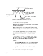
By pressing the
UP
button, from the main menu, you can step
through each of the modules to determine how they are programmed, if
they are receiving an input, and the source of that input. If a dimmer is
being driven from two inputs (for example Luma-Net and DMX512),
whichever input is higher has control, and that control type appears.