


a-2000 User Guide
a-2000
Page 43
Dimmer Cabinets with Digital Controls
Revision G November 2006
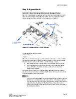
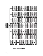
Step 8: Bypass Mode
Set 120 V Non Universal Dimmers to Bypass Mode:
Each 120 V dual dimmer is equipped with two 20-amp circuit breakers; one for
each circuit to be fed from that dimmer module. It is also equipped with two
dimmer bypass switches, adjacent to the breakers, see Figure 29.
Figure 29 - Bypass Switch - 120V Modules
The Bypass switch has two modes:
•
Normal and
•
Bypass.
When the switch is set to Bypass, all the dimmer electronics are removed from
the dimming circuit and the line is connected directly to load. Leviton normally
ships the dimmer cabinet with all these switches in Bypass mode.
1
After checking that all circuits come on and contain no short circuits,
2
Turn these switches to the Normal position. Once these switches are
turned to Normal, the dimmers and non-dims all operate in their
programmed condition.
If a dimmer fails to come on, the bypass switch associated with that dimmer
channel can be used to achieve full bright light output until repairs can be made
to the appropriate system components.
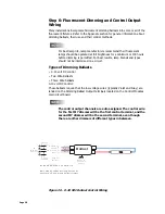
0-10 VDC controlled ballasts require an additional step to ensure that the
lights come to full brightness when the switch is in the Bypass position.
The purple control wire from the control terminals must be removed and
capped to allow the ballast to “float high.” Once this control wire is
removed and capped, the bypass switch can be used to force the lights to
the full bright condition.
Bypass Switches
Circuit Breakers
Top Of Dimmer
Cabinet