


Page 34
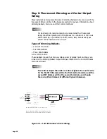
In order to use photocells in daylight harvesting applications, the analog
input card must be installed.
To connect the photocell to the a-2000, perform the following steps (reference
figures 24-25):
1
Connect the +0-10VDC output from the photocell to one of the a-2000
analog input terminals, labeled "Input 1, Input 2,... etc.
2
Connect the photocell common to the a-2000 input card
3
If the a-2000 +12VDC supply is powering the photocell, connect the
phoV and common supply leads to the +12V and common
terminals of the a-2000 analog input card.
The photocell manufacturer’s instructions must be followed explicitly to
ensure accurate results. Some photocells require a +24VDC supply. In
this case the photocell must be supplied from the +24 VDC remote
control panel power terminal.
When the above connections have been made correctly, and the programming
complete per page 71, the photocell will inversely control the output of
the dimmer level to reach the desired target level.
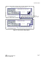
Figure 22 - Wiring Diagrams for One Photocell
Input 2
Common
+12 vdc
Input 1
Analog
Card
Common
Control Module
0-10 VDC
Input 3
Using a-2000 power
1 photo cell
V
V
V
To -10VDC
V
common
V
V
+12VDC


