


Page 24
Luma-Net® III
Power Considerations for Control Systems
The control system should be carefully planned out to take into consideration
these important issues:
•
Power Supply for Control Stations
•
Wire Size for Power Runs
On most systems, our applications engineering department has already managed
these calculations for you so this information should be irrelevant. However, if this
is not the case, like an ASAP (Quick Ship) program, when adding on to a system
or planning for a remodel, you will want to take this information into
consideration.
Power Requirements & Maximum Run Length
Each device on a Luma-Net network has a different load (draw) and each source
of power can support a different total load (supply.) To determine the total
capacity of your network, first determine the maximum supply current of your
power source, convert that to Unit Loads, then determine the total load it can
handle by summing the load of each device.
One Unit Load = 25mA
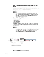
Figure 14 - Load Rating Verification Formula
The a-2000 cabinets are designed to be able to power either D4200 or D8000
stations from the internal power supply. See Table 7 for the available power from
each cabinet.
Table 7 -
Power Supply Maximum Unit Loads
Supply
Maximum # of Unit Loads
a-2000D, 12 Circuit,
Standard Power Supply
40
a-2000D, 24 Circuit
Standard Power Supply
24
NPC – XP
49
NPC – DHV
0 (no Luma-Net)
NPC – DLR
49
Control Station A Unit Load
X
Quantity of Station A's attached
+
Same formula
for any other attached
control Station
Control Station B Unit Load
X
Quantity of Station B's attached
<
+
Power Supply's
Available Unit Load


