


a-2000 User Guide
a-2000
Page 41
Dimmer Cabinets with Digital Controls
Revision G November 2006
Removal or Installation of Dimmer Module:
When the cabinets are shipped with the modules pre-installed, they are held in
place by a single sheet metal screw (#10-32). This screw is located on the left
side of the dimmer and securely holds each module to the cabinet for
transportation from the factory.
The dimmer modules simply plug in. No tools are required (except for
shipping screw when dimmer modules are pre-installed at factory) and
there is no risk of crossed wires when hooking up a new module.
If project drawings have been supplied by the factory and if the
dimmers are shipped separately, make sure that any special
dimmers are inserted into the proper module position within the
dimmer cabinet. These positions are marked in the cabinet and
shown on the installation diagrams provided with the system
and should also have a label inside the cabinet instructing where
these modules should be placed.
To remove a dimmer module:
1
Remove the shipping screw located on the left side of the module (if
installed).
2
Slide the module to the left to clear the power and control plugs until it
bumps the stop.
3
Lift it straight out of the cabinet.
To install a dimmer module into one of the positions
1
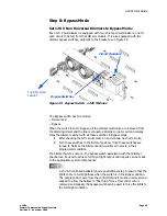
Remove the appropriate blanking plate(s) from the cabinet. There are
two plates per module location. One is located on the fan door. The
second is screwed down to the back pan. Start from the top and work
your way down (see Figure 27)
2
Place the heat sink notches over the two tabs while aligning the dimmer
module against the dimmer stop. Place the dimmer against the cabinet
pan. If the dimmer is not against the dimmer stop, the two notches will
not catch the two tabs on the pan.


