


a-2000 User Guide
a-2000
Page 31
Dimmer Cabinets with Digital Controls
Revision G November 2006
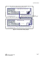
wiring for control stations should go to these terminals in the these
cabinets. These terminals are fed directly by the power supply and
accommodate larger wires and multiple wires per terminal section solving
power distribution problems for remote power controls.
Figure 20 - Control Station Power Wiring - Preferred Wiring Method
Testing the Wiring
To assure problem-free startup, it is important to check the system wiring for
proper connections, shorts and opens.
The following procedure is recommended:
Step 1:
Test the following wire pairs for shorts at each station location, using
an ohmmeter or other continuity tester.
1-2 Open
2-3 Open
3-4 Open
Step 2:
Repair any short circuits before continuing.
+24 VDC
COMMON
/54
$-8
,5-!.%4
2
%-
#
/--/.
.#
6
2%-
4%2-
).
$
3()%,$
3()%,$
$
$)--).'"!,,!34/540543
!583%2)!,
#!.
#!.(
#
/
--/.
23
$
$
3()%,$
23
4
2
#
/--/.
#
/--/.
#
/--/.
#
/--/.
3()%,$
#!.,
'2!9
/54
/.
'2!9
#
/--/.
#
/--/.
/54
6)/,%4
/54
/54
/54
/54
/54
/54
#
/--/.
#
/--/.
!,,
).054
6$#
A$IGITAL
-AIN#ONTROL-ODULE
#LASS#ONTROL
2%-/
4%#
/.42/,0
!.%,0/7%2
6$#
$#
##
/--/.
,/
!$7)2%3
4O
RQ
UEINLBS
7IR
E2
ANGE!
7'
5
SE#
OPPER7IR
E/NLY
7)2%#
/-").!
4)/.3
!
4"
4"
4"
4"
4"
-!$%).4(%53!
#,%6)4/.-&'#/
!,,2)'(432%3%26%$
4"
"
#
4"
!
#/--5.)#!4)/.0/243
&5,,"2)'(4
!58),)!29
,5-!.%4
0(!3%,/33
$-8
&!.
"2)'(4
3%,%#4
#!.#%,
&5,,
3!6%
#,%!2
4"
4"
6
).054
,%&4#/..%#4/2
!.!,/').05436$#
6
).054
#
/--/.
).054
).054
).054
).054
).054
).054
).054
).054
).054
#
/--/.
).054
6
).054
2)'(4#/..%#4/2
!.!,/').05436$#
6
).054
#
/--/.
).054
).054
).054
).054
).054
).054
).054
).054
).054
#
/--/.
).054
2%-/
4%#
/.42/,0
!.%,0/7%2
6$#
$#
##
/--/.
,/
!$7)2%3
4O
RQUEINLBS
7IR
E2
ANGE!
7'
5
SE#
OPPER7IR
E/NLY
7)2%#
/-").!
4)/.3
!


