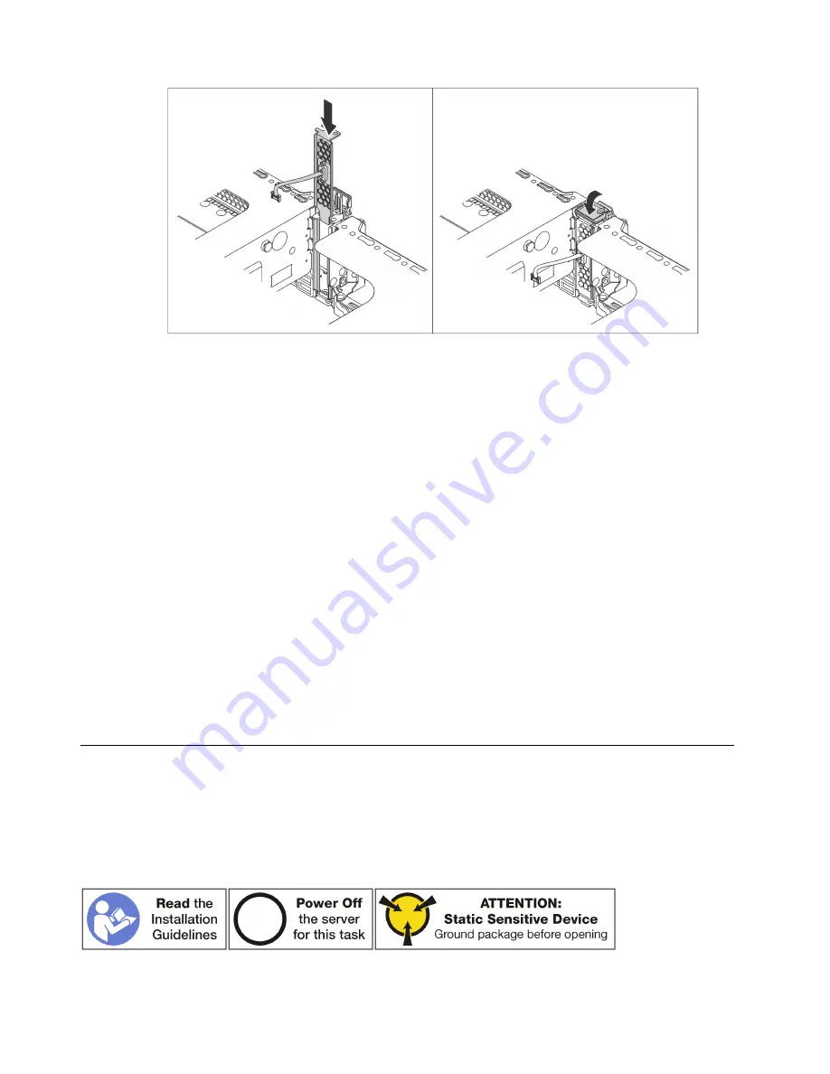
Figure 129. Serial port module installation
Step 2. Connect the cable of the serial port module to the serial-port-module connector on the system
board. For the location of the serial-port-module connector, refer to “System board components”
on page 23.
After installing the serial port module:
1. Complete the parts replacement. See “Complete the parts replacement” on page 203.
2. To enable the serial port module, do one of the following according to the installed operating system:
• For Linux operating system:
Open the ipmitool and enter the following command to disable the Serial over LAN (SOL) feature:
-I lanplus -H IP -U USERID -P PASSW0RD sol deactivate
• For Microsoft Windows operating system:
a. Open the ipmitool and enter the following command to disable the SOL feature:
-I lanplus -H IP -U USERID -P PASSW0RD sol deactivate
b. Open Windows PowerShell and enter the following command to disable the Emergency
Management Services (EMS) feature:
Bcdedit / ems no
c. Restart the server to ensure that the EMS setting takes effect.
M.2 backplane and M.2 drive replacement
Use this information to remove and install the M.2 backplane and M.2 drive (an assembled M.2 backplane
and M.2 drive also known as M.2 module).
Remove the M.2 backplane and M.2 drive
Use this information to remove the M.2 backplane and M.2 drive.
166
ThinkSystem SR650 Maintenance Manual
Summary of Contents for ThinkSystem SR650
Page 1: ...ThinkSystem SR650 Maintenance Manual Machine Types 7X05 and 7X06 ...
Page 8: ...vi ThinkSystem SR650 Maintenance Manual ...
Page 20: ...12 ThinkSystem SR650 Maintenance Manual ...
Page 96: ...88 ThinkSystem SR650 Maintenance Manual ...
Page 154: ...Figure 107 Riser 1 assembly removal 146 ThinkSystem SR650 Maintenance Manual ...
Page 212: ...204 ThinkSystem SR650 Maintenance Manual ...
Page 230: ...222 ThinkSystem SR650 Maintenance Manual ...
Page 234: ...226 ThinkSystem SR650 Maintenance Manual ...
Page 243: ......
Page 244: ......


