Chapter 5. Locating Server Controls and connectors
This section describes the controls and light-emitting diodes (LEDs) and how to
turn the server on and off.
Front view
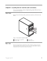
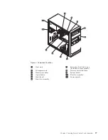
Figure 1 shows the locations of the controls and connectors on the front of your
server.
1
Hard disk drive activity LED
3
Power switch
2
Power-on LED
4
USB connectors (2)
Rear view
Figure 2 on page 24 shows the locations of the connectors on the rear of your
server. Some connectors on the rear of your server are color-coded to help you
determine where to connect the cables in your server.
Figure 1. Front control and connector locations
© Copyright Lenovo 2010
23
Summary of Contents for ThinkServer TS200v
Page 1: ......
Page 2: ......
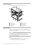
Page 3: ...ThinkServer TS200v Types 0981 0992 1008 and 1010 Hardware Maintenance Manual ...
Page 28: ...22 ThinkServer TS200v Types 0981 0992 1008 and 1010 Hardware Maintenance Manual ...
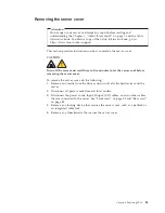
Page 34: ...28 ThinkServer TS200v Types 0981 0992 1008 and 1010 Hardware Maintenance Manual ...
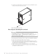
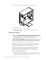
Page 84: ...78 ThinkServer TS200v Types 0981 0992 1008 and 1010 Hardware Maintenance Manual ...
Page 107: ......
Page 108: ...Part Number XXXXXX Printed in USA 1P P N XXXXXX ...


