


5. Disconnect the cable of the power switch unit from the system board.
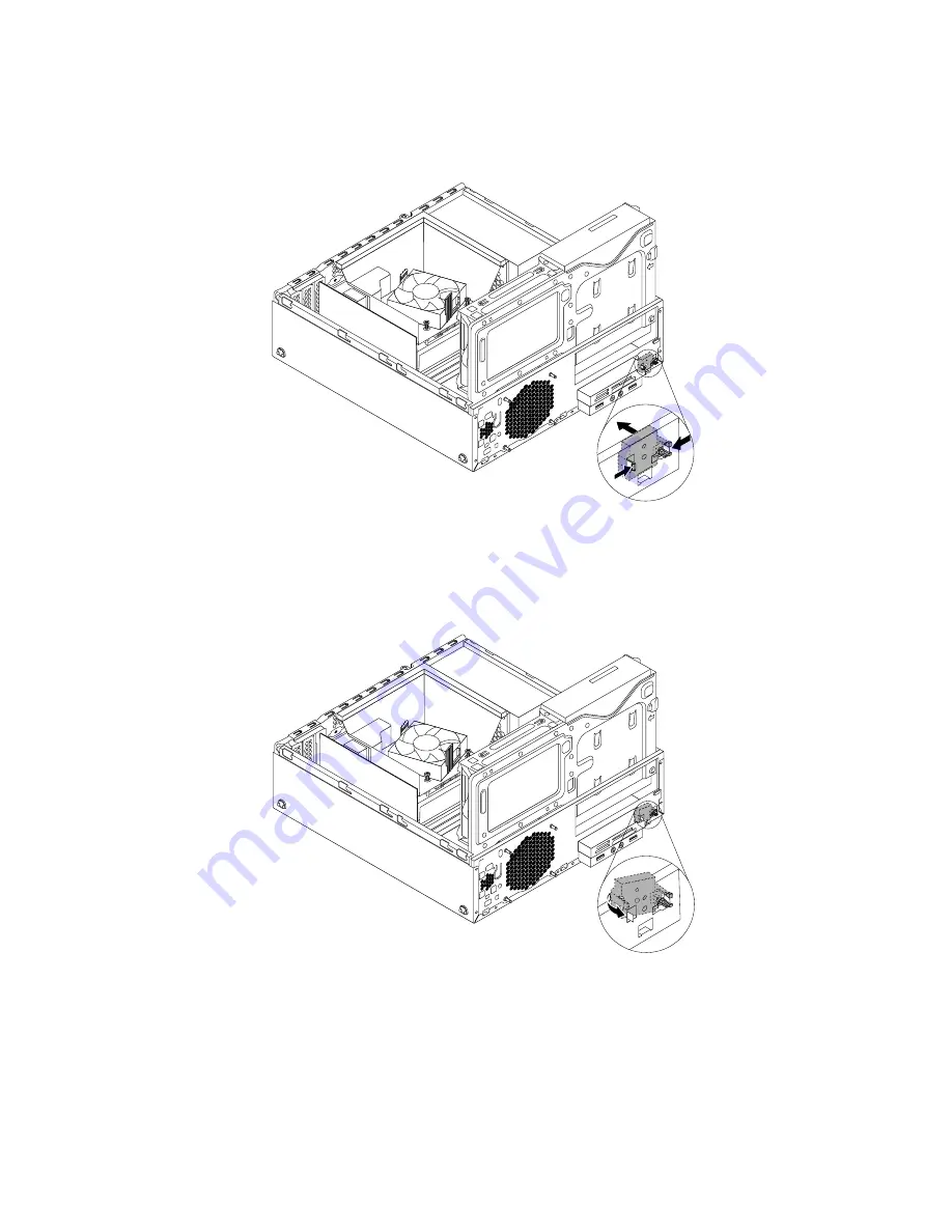
6. Push the power switch unit inward through the hole to disengage it from the chassis.
Figure 151. Removing the power switch unit
7. Insert the two plastic tabs on the side of the new power switch unit through the hole in the chassis, and
then press the power switch unit as shown until it snaps into position.
Figure 152. Installing the power switch unit
8. Connect the cable of the new power switch unit to the system board. See “Locating parts on the
system board” on page 82.
9. Reinstall the front bezel. See “Removing and reinstalling the front bezel” on page 160.
What to do next:
• To work with another piece of hardware, go to the appropriate section.
190
ThinkCentre M83 and M93/p Hardware Maintenance Manual
Summary of Contents for ThinkCentre M83
Page 6: ...iv ThinkCentre M83 and M93 p Hardware Maintenance Manual ...
Page 8: ...vi ThinkCentre M83 and M93 p Hardware Maintenance Manual ...
Page 15: ...Chapter 1 Safety information 7 ...
Page 19: ...Chapter 1 Safety information 11 ...
Page 20: ...1 2 12 ThinkCentre M83 and M93 p Hardware Maintenance Manual ...
Page 21: ...1 2 Chapter 1 Safety information 13 ...
Page 26: ...1 2 18 ThinkCentre M83 and M93 p Hardware Maintenance Manual ...
Page 27: ...1 2 Chapter 1 Safety information 19 ...
Page 30: ...22 ThinkCentre M83 and M93 p Hardware Maintenance Manual ...
Page 34: ...26 ThinkCentre M83 and M93 p Hardware Maintenance Manual ...
Page 40: ...32 ThinkCentre M83 and M93 p Hardware Maintenance Manual ...
Page 74: ...66 ThinkCentre M83 and M93 p Hardware Maintenance Manual ...
Page 100: ...92 ThinkCentre M83 and M93 p Hardware Maintenance Manual ...
Page 166: ...158 ThinkCentre M83 and M93 p Hardware Maintenance Manual ...
Page 306: ...298 ThinkCentre M83 and M93 p Hardware Maintenance Manual ...
Page 307: ......
Page 308: ......


