


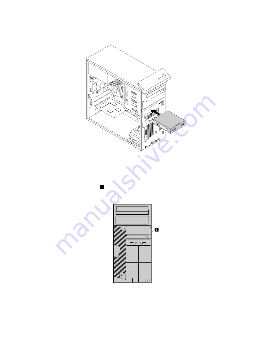
7. Slide the new front USB assembly with retainer into the card reader drive bay until it snaps into position.
Figure 40. Installing the front USB assembly
8. Connect the front USB assembly cable to the front USB connector 2 on the system board. See
“Locating parts on the system board” on page 72.
9. Locate the protective cover for the card reader drive bay on the front bezel. Remove the protective
cover by pressing the small tabs
1
to the left, and then pulling the tabs to completely disengage
the cover from the front bezel.
Figure 41. Removing the card reader cover
10. Reinstall the front bezel. See “Removing and reinstalling the front bezel” on page 94.
108
ThinkCentre M83 and M93/p Hardware Maintenance Manual
Summary of Contents for ThinkCentre M83
Page 6: ...iv ThinkCentre M83 and M93 p Hardware Maintenance Manual ...
Page 8: ...vi ThinkCentre M83 and M93 p Hardware Maintenance Manual ...
Page 15: ...Chapter 1 Safety information 7 ...
Page 19: ...Chapter 1 Safety information 11 ...
Page 20: ...1 2 12 ThinkCentre M83 and M93 p Hardware Maintenance Manual ...
Page 21: ...1 2 Chapter 1 Safety information 13 ...
Page 26: ...1 2 18 ThinkCentre M83 and M93 p Hardware Maintenance Manual ...
Page 27: ...1 2 Chapter 1 Safety information 19 ...
Page 30: ...22 ThinkCentre M83 and M93 p Hardware Maintenance Manual ...
Page 34: ...26 ThinkCentre M83 and M93 p Hardware Maintenance Manual ...
Page 40: ...32 ThinkCentre M83 and M93 p Hardware Maintenance Manual ...
Page 74: ...66 ThinkCentre M83 and M93 p Hardware Maintenance Manual ...
Page 100: ...92 ThinkCentre M83 and M93 p Hardware Maintenance Manual ...
Page 166: ...158 ThinkCentre M83 and M93 p Hardware Maintenance Manual ...
Page 306: ...298 ThinkCentre M83 and M93 p Hardware Maintenance Manual ...
Page 307: ......
Page 308: ......


