


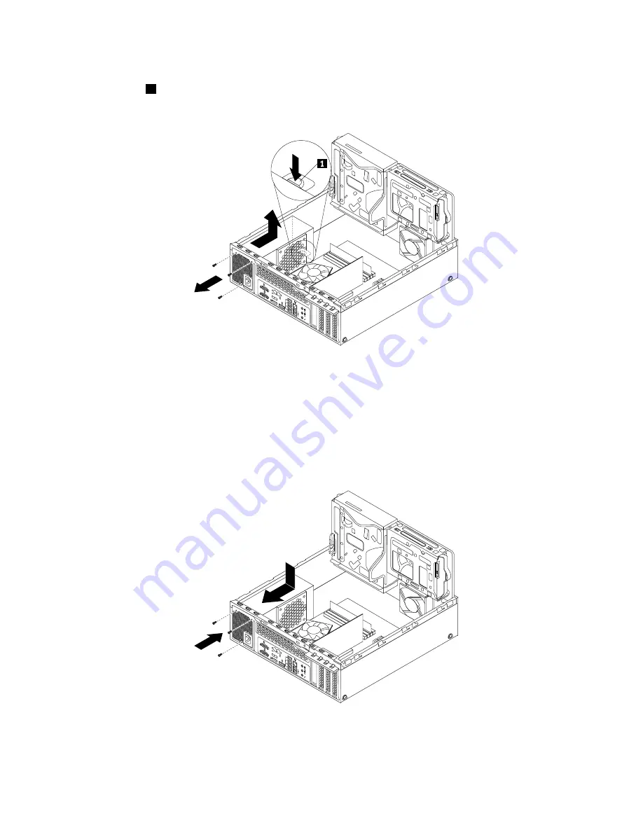
8. At the rear of the computer, remove the three screws that secure the power supply assembly. Press the
retaining clip
1
downward and slide the power supply assembly to the front of the computer. Then, lift
the power supply assembly out of the computer.
3
4
5
6
7
8
Figure 148. Removing the power supply assembly
9. Ensure that the new power supply assembly is the correct replacement.
10. Install the new power supply assembly into the chassis so that the screw holes in the new power supply
assembly are aligned with the corresponding holes in the rear of the chassis. Then, install the three
screws to secure the new power supply assembly.
Note:
Use only screws provided by Lenovo.
3
4
5
6
7
8
Figure 149. Installing the power supply assembly
188
ThinkCentre M83 and M93/p Hardware Maintenance Manual
Summary of Contents for ThinkCentre M83
Page 6: ...iv ThinkCentre M83 and M93 p Hardware Maintenance Manual ...
Page 8: ...vi ThinkCentre M83 and M93 p Hardware Maintenance Manual ...
Page 15: ...Chapter 1 Safety information 7 ...
Page 19: ...Chapter 1 Safety information 11 ...
Page 20: ...1 2 12 ThinkCentre M83 and M93 p Hardware Maintenance Manual ...
Page 21: ...1 2 Chapter 1 Safety information 13 ...
Page 26: ...1 2 18 ThinkCentre M83 and M93 p Hardware Maintenance Manual ...
Page 27: ...1 2 Chapter 1 Safety information 19 ...
Page 30: ...22 ThinkCentre M83 and M93 p Hardware Maintenance Manual ...
Page 34: ...26 ThinkCentre M83 and M93 p Hardware Maintenance Manual ...
Page 40: ...32 ThinkCentre M83 and M93 p Hardware Maintenance Manual ...
Page 74: ...66 ThinkCentre M83 and M93 p Hardware Maintenance Manual ...
Page 100: ...92 ThinkCentre M83 and M93 p Hardware Maintenance Manual ...
Page 166: ...158 ThinkCentre M83 and M93 p Hardware Maintenance Manual ...
Page 306: ...298 ThinkCentre M83 and M93 p Hardware Maintenance Manual ...
Page 307: ......
Page 308: ......


