


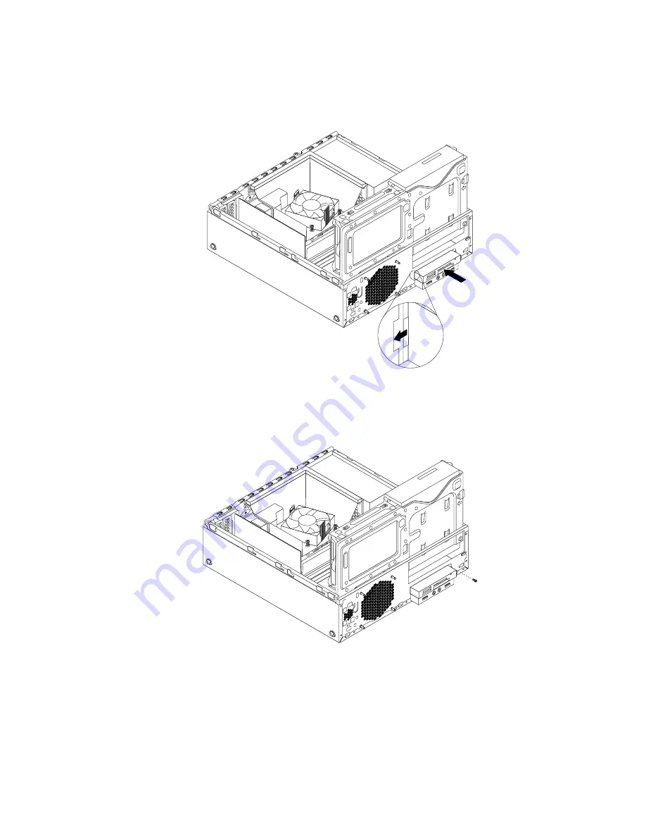
7. Install the new card reader assembly into the card reader drive bay until it snaps into position. Then,
push the new card reader assembly to the left until the screw hole in the metal bracket of the card
reader assembly is aligned with the corresponding hole in the chassis.
Figure 122. Installing the card reader assembly
8. Install the screw to secure the card reader assembly to the chassis.
Figure 123. Installing the screw to secure the card reader assembly
9. Connect the cable of the new card reader assembly to the front USB connector 1 on the system board.
See “Locating parts on the system board” on page 82
What to do next:
• To work with another piece of hardware, go to the appropriate section.
• To complete the installation or replacement, go to “Completing the parts replacement” on page 234.
Chapter 9
.
Replacing FRUs (machine types: 10A2, 10A3, 10A8, 10A9, 10AH, 10AJ, 10AM, and 10AN)
173
Summary of Contents for ThinkCentre M83
Page 6: ...iv ThinkCentre M83 and M93 p Hardware Maintenance Manual ...
Page 8: ...vi ThinkCentre M83 and M93 p Hardware Maintenance Manual ...
Page 15: ...Chapter 1 Safety information 7 ...
Page 19: ...Chapter 1 Safety information 11 ...
Page 20: ...1 2 12 ThinkCentre M83 and M93 p Hardware Maintenance Manual ...
Page 21: ...1 2 Chapter 1 Safety information 13 ...
Page 26: ...1 2 18 ThinkCentre M83 and M93 p Hardware Maintenance Manual ...
Page 27: ...1 2 Chapter 1 Safety information 19 ...
Page 30: ...22 ThinkCentre M83 and M93 p Hardware Maintenance Manual ...
Page 34: ...26 ThinkCentre M83 and M93 p Hardware Maintenance Manual ...
Page 40: ...32 ThinkCentre M83 and M93 p Hardware Maintenance Manual ...
Page 74: ...66 ThinkCentre M83 and M93 p Hardware Maintenance Manual ...
Page 100: ...92 ThinkCentre M83 and M93 p Hardware Maintenance Manual ...
Page 166: ...158 ThinkCentre M83 and M93 p Hardware Maintenance Manual ...
Page 306: ...298 ThinkCentre M83 and M93 p Hardware Maintenance Manual ...
Page 307: ......
Page 308: ......


