


Figure 26. Connecting the NVMe cables to the processor and memory expansion tray
Before starting cable routing for 2.5-inch drives:
1. Remove the fan cage assembly (see
“Remove the fan cage assembly” on page 98
2. Remove the system board air baffle (see
“Remove the system board air baffle and the power interposer”
) or the processor and memory expansion tray and the processor and memory expansion tray
air baffle (see
“Remove the processor and memory expansion tray” on page 96
).
Connecting power cable
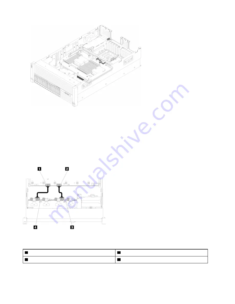
Connect power cables for drive backplanes as in the following illustration.
Figure 27. Location of power cable connectors on the system board
Table 21. Power cable connectors on the system board and the drive backplanes
1
Power cable connector on the system board
3
Power cable connector on the drive backplane
2
Power cable connector on the system board
4
Power cable connector on the drive backplane
Two types of drive backplanes are supported by this system:
32
ThinkSystem SR860 Setup Guide
Summary of Contents for 7X69
Page 1: ...ThinkSystem SR860 Setup Guide Machine Type 7X69 and 7X70 ...
Page 8: ...vi ThinkSystem SR860 Setup Guide ...
Page 62: ...54 ThinkSystem SR860 Setup Guide ...
Page 69: ...Chapter 3 Server hardware setup 61 ...
Page 82: ...74 ThinkSystem SR860 Setup Guide ...
Page 108: ...100 ThinkSystem SR860 Setup Guide ...
Page 162: ...154 ThinkSystem SR860 Setup Guide ...
Page 166: ...158 ThinkSystem SR860 Setup Guide ...
Page 171: ......
Page 172: ...Part Number SP47A30799 Printed in China 1P P N SP47A30799 1PSP47A30799 ...


