Locating parts on the system board
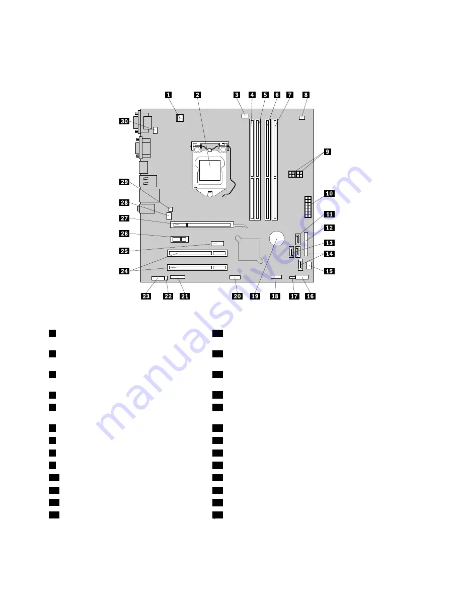
Figure 4 “System board part locations” on page 72 shows the locations of the parts on the system board.
Figure 4. System board part locations
1
4-pin power connector
16
Front panel connector (for connecting LED indicators and
power switch)
2
Microprocessor
17
Clear CMOS (Complementary Metal Oxide Semiconductor)
/Recovery jumper
3
Microprocessor fan connector
18
Front USB connector 1 (for connecting USB ports 1 and 2
on the front bezel)
4
Memory slot 1 (DIMM 1)
19
Battery
5
Memory slot 2 (DIMM 2)
20
Front USB connector 2 (for connecting additional USB
devices)
6
Memory slot 3 (DIMM 3)
21
Serial (COM2) connector
7
Memory slot 4 (DIMM 4)
22
Internal speaker connector
8
Thermal sensor connector
23
Front audio connector
9
4-pin power connectors (2)
24
PCI card slots (2)
10
14-pin power connector
25
DisplayPort connector
11
SATA connector (SATA 3.0 connector)
26
PCI Express x1 card slot
12
Parallel connector
27
PCI Express x16 graphics card slot
13
eSATA connector
28
System fan connector
72
ThinkCentre Edge Hardware Maintenance Manual
Summary of Contents for 3376
Page 1: ...ThinkCentre Edge Hardware Maintenance Manual Machine Types 3376 3377 3378 3386 3387 and 3388 ...
Page 6: ...2 ThinkCentre Edge Hardware Maintenance Manual ...
Page 13: ...Chapter 2 Safety information 9 ...
Page 17: ...Chapter 2 Safety information 13 ...
Page 18: ...1 2 14 ThinkCentre Edge Hardware Maintenance Manual ...
Page 19: ...1 2 Chapter 2 Safety information 15 ...
Page 24: ...1 2 20 ThinkCentre Edge Hardware Maintenance Manual ...
Page 25: ...1 2 Chapter 2 Safety information 21 ...
Page 28: ...24 ThinkCentre Edge Hardware Maintenance Manual ...
Page 32: ...28 ThinkCentre Edge Hardware Maintenance Manual ...
Page 58: ...54 ThinkCentre Edge Hardware Maintenance Manual ...
Page 122: ...118 ThinkCentre Edge Hardware Maintenance Manual ...
Page 164: ...160 ThinkCentre Edge Hardware Maintenance Manual ...
Page 173: ......


