Page 8
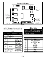
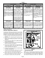
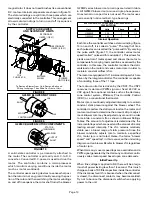
To change jumper positions, gently pull the jumper off the
pins and place it on the desired set of pins. The following
section outlines the different jumper selections available
and conditions associated with each one. Refer to figure 4
for identification.
After the CFM for each application has been determined,
the jumper settings must be adjusted to reflect those
given in the tables on page 2. Using the tables, determine
which row of CFM volumes most closely matches the
desired CFM. Once a specific row has been chosen
(NORMAL or –), CFM volumes from other rows cannot
be used. Below are the descriptions of each of the
jumper selections.
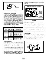
Refer to table 4 for factory settings. Refer to the tables on
page 2 for the approximate air volume for each setting.
TABLE 4
MODEL
NUMBER
G25MV3-60
G25MV3-75
VSP2–1 FACTORY SETTINGS
HIGH
LOW
HEAT
1
4
1
2
4
3
ADJUST
NORM
NORM
G25MV5-100
2
4
1
2
4
3
NORM
NORM
G25MV5-120
The
ADJUST
pins allow the motor to run at normal speed
or approximately 10% lower than normal speed. The
tables on page 2 give two rows (NORMAL and –) with
their respective CFM volumes. The + adjustment setting
is not operable. Notice that the normal adjustment
setting for heat speed position #3 is 2030 CFM (960
L/s). After the adjustment setting has been determined,
chose the remaining speed jumper settings from
those offered in the table.
The TEST pin is available to bypass the VSP2–1 control
and run the motor at approximately 70% to test that the
motor is operational. This is beneficial primarily in
troubleshooting. G must be energized for motor to run.
For G25MV units, place the
jumper
across the second and third pins (position #2).
When W1 is energized, the
jumper selections are
activated. The
HEAT
jumper selections are activated
when W2 is energized.
NOTE–In Harmony II zoning applications, HEATING
BLOWER jumper must be in position #2.
The
HEAT
jumper is used to set the blower speed to
obtain the required CFM as outlined in HEAT SPEED
section of the tables on page 2.
The
HEAT
jumper selections are activated with a call for
second-stage heating (W2).
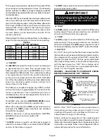
IMPORTANT
Before changing jumper setting, make sure the
motor has completely stopped. Any jumper set-
ting change will not take place while the motor
is running.
The
HIGH
jumper is used to determine the CFM during
cooling speed. These jumper selections are activated
when G and DS terminals are energized.
The
LOW
jumper is used to determine CFM during low
speed cooling. These jumper selections are activated
when G is energized. The
LOW
jumper may also be used
for low speed heating. See the “HEAT” section for details.
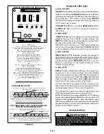
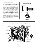
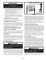
Fan “OFF” timings (time that the blower operates after
the heat demand has been satisfied) are determined by
the arrangement of a jumper on the VSP2–1 board. See
figure 6. To adjust fan “OFF” timings, gently disconnect
the jumper and reposition it across pins corresponding
with the new timing. Fan “OFF” time is factory set at
270 seconds. The control has a non–adjustable, factory
preset “on” fan timing (45 seconds).
FIGURE 6
FAN-OFF TIME ADJUSTMENT
270
210
150
90
To adjust fan–off timings:
Remove jumper from VSP2–1 and
select one of the other pin com-
binations to achieve the desired
time.
TIMING
JUMPER
TIMING PINS (seconds)
Leave jumper off to achieve
330 second fan–off timing.
Fan-off timing is factory
set at 270 seconds
NOTE—If fan “OFF” time is too low, residual heat in
heat exchanger may cause primary limit S10 to trip
resulting in frequent cycling of blower. If this occurs,
adjust blower to longer time setting.
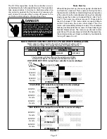
Table 5 outlines the operation of the variable speed
motor in relation to specific modes of operation. Some
information has been repeated from the previous section
to provide an example. Refer to each diagnostic LED or
jumper settings section for more information.


