Page 21
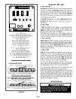
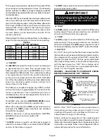
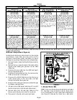
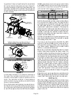
VII–WIRING DIAGRAM AND SEQUENCE OF OPERATION
5
1
2
3
4
7
6
8
9
10
10
5
10
2
3
4
10
5
G25MV OPERATION SEQUENCE
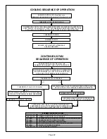
(FOR A MORE DETAILED DESCRIPTION SEE THE FLOW CHARTS ON THE FOLLOWING TWO PAGES):
1- When disconnect is closed, 120V is routed through
door interlock switch (S51) to feed the line voltage
side of the ignition control (A3) and transformer (T1)
primary. Door interlock switch must be closed for A3
and T1 to receive voltage.
2- T1 supplies 24VAC to terminal “24VAC” on A3. In
turn, terminal “R” of A3 supplies 24VAC to the indoor
thermostat (not shown).
3- Upon first stage (W1) call for heat from the thermo-
stat, W1 of the burner control (A3) is powered. If the
flue box thermostat (S101) is closed, then high fire is
energized. If S101 is open, then low fire is energized.
4- Upon second stage (W2) call for heat from the
thermostat, W1 and W2 of the burner control (A3)
are powered and high fire will be energized regard-
less of S101 being opened or closed. Once second
stage is satisfied, high fire will cycle back to low fire,
provided S101 is open.
5- The combustion air blower (B6) is energized by
A3. If the gas valve is energized on high fire, then
B6 is energized on high speed, if the gas valve is
energized on low fire, then B6 is energized on low
speed. When the combustion air blower nears low or
high operating speed, combustion air prove switches
(S72 – low fire and S102 – high fire) close.
6- When S72 and S102 close (assuming the primary
limit (S10), flame rollout switches (S47), and second-
ary limits [(1)S21 and (2)S21] are closed), the burner
control begins a 30-second time-delay (pre-purge).
7- At the end of the pre-purge cycle, A3 energizes the hot
surface ignitor for a 35 second warm up period.
8- At the end of the warm up period, the gas valve
(GV1) is energized for 7 seconds (maximum trial
for ignition period).
9- When flame is sensed, the hot surface ignitor is
de-energized and VSP2 control (A24) begins a
45-second delay before energizing the indoor blower.
10- When heat demand is satisfied, the thermostat
de-energizes W1 of the burner control (A3) and
A3 immediately de-energizes the gas valve. The
combustion air blower runs for 5 seconds (post-
purge) before being de-energized. Also, the indoor
blower runs for a designated period (90-270 seconds)
as set by the timing jumper on VSP2 control A24.

