Page 14
Top
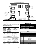
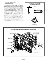
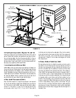
G25MV BURNER ASSEMBLY (shown in upflow position)
FIGURE 16
HOT SURFACE
IGNITOR
FLAME
SENSOR
MANIFOLD
ORIFICE
GAS VALVE
(GV1)
HEAT EXCHANGER
BURNER
UPPER
BURNER
MOUNTING
RAIL
LOWER
BURNER
MOUNTING
RAIL
BURNER BOX
BURNER BOX
TOP
ROLLOUT
SWITCHES (S47)
Front
Right
Bottom
Left
Back
PRIMARY LIMIT (S10)
VEST PANEL
C–Heating Components (Figures 15 and 16)
Heating components are located inside the front louvered
panel. Inside the heating compartment are the combus-
tion air blower (B6), flue limit thermostat (S101), flame
rollout switches (S47), primary limit control (S10), ignitor,
flame sensor, gas valve (GV1), and the combustion air
blower prove switches (S72 and S102).
1–Combustion Air Blower (B6)
All G25MV units use a two stage combustion air blower to
move air through the burners and heat exchanger during
heating operation. The blower uses a 120VAC motor. The
motor operates during all heating operation and is con-
trolled by burner control A3. The blower also operates for
30 seconds before burner ignition (pre-purge) and for 5
seconds after the gas valve closes (post-purge).
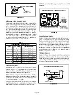
2–Flue Limit Thermostat (S101)
Flue limit thermostat is a high temperature limit located
on top of combustion air blower collector box (see figure
15). The limit is a N.C. SPST auto-reset limit which opens
at 200
F + 5
F (93.3
C + 2.8
C) on a temperature rise
and closes at 160
F + 8
F (71.1
C + 4.4
C). The switch
is factory set and cannot be adjusted. The limit is electri-
cally connected to the burner control A3. The purpose of
the limit is to set the unit to low fire when temperature
reaches 200
F (93.3
C) in the heat exchanger on call for
first stage heat.
3–Flame Rollout Switches (S47)
Flame rollout switch is a high temperature limit switch
located on top of the burner box (see figure 16). Each
furnace is equipped with two identical switches. One
switch is located over the leftmost burner and the other
switch is located over the rightmost burner. The switch is
a N.C. SPST manual-reset switch which actuates at 267
F
+ 12
F (130.5
C + 6.7
C) on a temperature rise. The switch
is factory set and cannot be adjusted. To manually reset
a tripped switch, push the reset button located on the
control. The switches are connected in series with the
burner control A3. When S47 senses rollout, the burner
control immediately stops ignition and closes the gas
valve. If unit is running and flame rollout is detected, the
gas valve will close and ignition control will be disabled.
Rollout can be caused by a clogged heat exchanger or a
blocked flue.


