Page 5
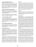
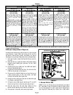
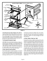
G25MV BURNER CONTROL (A3)
FIGURE 3
LINE VOLTAGE
TERMINAL
CONNECTIONS
24VAC VOLT
TERMINAL
CONNECTIONS
THERMOSTAT
CONNECTIONS (TB1)
DIAGNOSTIC
LED
See Table 3 for
Terminal
Functions
PLUG P20
12
1
See Table 2 for
Terminal
Functions
3
Diagnostic LED
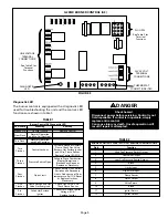
The burner control is equipped with a diagnostic LED
used for troubleshooting the unit and the control. LED
functions are shown in table 1.
TABLE 1
Burner Control A3 Diagnostic LED
LED State
Meaning
Remedy
Steady On
Control Failure
Replace Control
Slow Flash
Normal Operation
and No Call For Heat
- - - -
Fast Flash
Normal Operation
with Call For Heat
- - - -
Two
Flashes
Control Lockout
Failed to Sense or Sustain
Flame. Check Gas Valve,
Burners, Hot Surface Ignitor
and Wire, Flame Sensor.
Replace Control If All OK.
Three
Flashes
Pressure Switch Open
Failed to Prove Combustion
Blower Operation or
Blocked Vent. Repair or
Replace as Necessary.
Four
Flashes
Open Limit
Check Primary Limit, Rollout
Switches and Secondary
Limits. Find source of Over
temperature. If all OK, Reset
or Replace Limits as
Necessary.
Five
Flashes
Flame Sensed and Gas
Valve Not Energized.
Check Gas Valve. If OK,
Check Flame Sensor.
Six
Flashes
Failed Hot Surface
Ignitor
Check Hot Surface Ignitor
Voltage. If OK,
Replace Ignitor
DANGER
Shock hazard.
Disconnect power before servicing. Control is not
field repairable. If control is inoperable, simply
replace entire control.
Can cause injury or death. Unsafe operation will
result if repair is attempted.
TABLE 2
BURNER CONTROL JACK/PLUG 20 TERMINAL DESIGNATIONS
Pin #
Function
1
High Fire Pressure Switch Output
2
Low Valve Output
3
Low Fire Pressure Switch Output
4
Blank
5
Limits Input
6
High Limit Input
7
Flame Sensor
8
Limits Output
9
Valve Return
10
Blank
11
Ignitor Return
12
Ignitor Output


