


²
&DSWXULQJ*OLWFKHV
Note: The Glitch SMART
Trigger is the particular variety
selected by default. It will be
used here, but pressing the
menu button for “SETUP
SMART TRIGGER” will show
the other types of SMART
Trigger available.
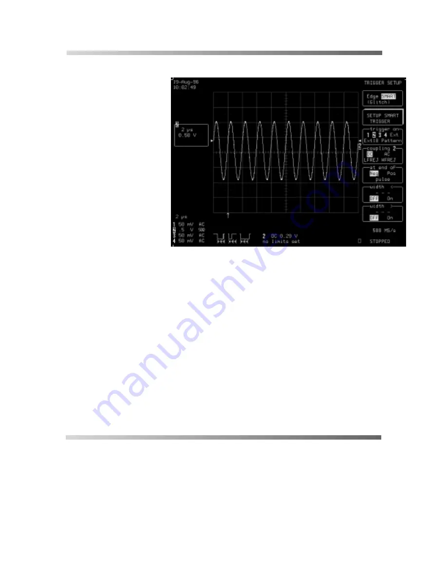
Source and coupling were set
in the preceding steps. The
slope can now be selected —
“
1HJ
” (negative) or “Pos”
(positive). The icon displayed
under the grid represents and
describes the trigger setup.
The next step is to set the trigger to capture the glitch on the current
signal.
Here, the glitch’s width is lower than the signal’s. Thus the trigger
needs to be set to a smaller width than that of the signal, whose own
width depends on the DC trigger level. If that level is set at the middle
of the sinewave, the width can be considered as the half period.
However, if the level is higher, the signal’s width has to be considered
as being less than the half-period. Two microseconds is the period for
our example sinewave. The DC trigger level is set, not at the middle
of the sinewave, but where its width is about 800 ns.
Therefore, the Glitch SMART trigger ought to be on CH 2 at end of
“Neg” pulse with a width of < 800 ns.
Summary of Contents for Digital Oscilloscopes
Page 1: ...Hands On Guide to LeCroy Color Digital Oscilloscopes Revision C April 1998 ...
Page 21: ... ...
Page 36: ... HWWLQJ 6WDUWHG Now press the corresponding to select REDEFINE These menus will appear ...
Page 45: ... 0HDVXULQJ 6NLOOV 67 3 Press again The screen will then display ...
Page 49: ... 0HDVXULQJ 6NLOOV The screen will now display ...
Page 74: ... QDORJ 3HUVLVWHQFH The screen will then display 67 3 Press ...
Page 93: ... 0HDVXULQJ 6NLOOV ...
Page 127: ... 0HDVXULQJ 6NLOOV ...
Page 175: ... 0HDVXULQJ 6NLOOV ...
Page 177: ... 0HDVXULQJ 6NLOOV 67 3 Press again to display 67 3 Press and then ...


