LT-3100S GMDSS User & Installation Manual Rev. 1.02
Interfaces
Lars Thrane A/S
www.thrane.eu
Page 26 of 71
LT-3130 Antenna Unit
The LT-3110S Control Unit and the LT-3130 Antenna Unit must be connected using a coaxial cable. Both the
control unit and the antenna unit has a N connector (female) mounted. This section will specify the
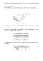
requirements to the coaxial cable. The minimum set of requirements are specified in Table 5 and Figure 29.
In most cases it will be the DC resistance that will determine the maximum length of the coaxial cable. It is
important to note that the input voltage of the control unit is important for the length of the coaxial cable
that can be used. The following formula can be used to calculate the length of the coaxial cable:
𝐶𝑎𝑏𝑙𝑒 𝐿𝑒𝑛𝑔𝑡ℎ (𝑚) =
𝑈
2
∗ 1000
4 ∗ 𝑃
𝐷
∗ 𝑅
𝐶𝑎𝑏𝑙𝑒
where U is the control unit input voltage [V], P
D
is the antenna unit power (10 W), and R
Cable
is the total DC
resistance [
ꭥ
/km] (sum of inner and outer conductor resistance).
Figure 29: Coaxial Cable Total DC Resistance vs. Cable Length (12 VDC and 24 VDC).
Cable impedance
50 Ω
Maximum signal loss
47.7 dB/100 m @ 1.5 GHz
Maximum DC resistance
Table 5: Minimum requirements for the coaxial cable connecting the LT-3110S
Control Unit and LT-3130 Antenna Unit.

