LT-3100S GMDSS User & Installation Manual Rev. 1.02
Installation and Mounting
Lars Thrane A/S
www.thrane.eu
Page 19 of 71
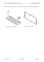
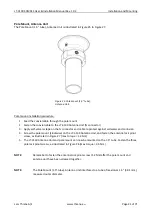
Bracket Mount, Antenna Unit
The
Bracket Mount (1.5” to 2.5”
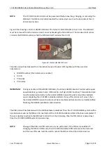
tube), Antenna Unit installation options are illustrated in Figure 21 to
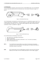
Bracket mount installation procedure:
1.
Fasten the bracket mount to a tube
(max. 2.5“ tube) by using the two V
-bolts and the M8 prevailing
nuts, as illustrated in Figure 24 on page 20 (max torque = 5.5 Nm)
2.
Screw on the LT-3130 Antenna Unit and secure the antenna lock pinot (max torque = 1.2 Nm)
3.
Fasten the coaxial cable to the LT-3130 Antenna Unit (N connector)
4.
Apply self-volcanic tape on the N connector and cable to protect against saltwater and corrosion
NOTE
:
Always fasten the Bracket Mount, Antenna Unit (1.5” to 2.5”
tube) to the tube, before
installing the LT-3130 Antenna Unit (the antenna unit and bracket mount are fastened
together by the thread lock). Remember to secure the pinot screw after the antenna unit
has been fastened. The torques are specified in Figure 24 on page 20.
NOTE
:
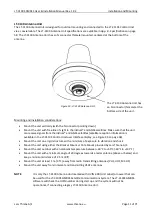
The Bracket Mount (1.5” to 2.5” tube), Antenna Unit
interfaces to a tube of maximum 2.
5”
(63.5 mm), measured outer diameter.
Figure 22: Bracket Mount
(1.5” to 2.5”
tube), Antenna Unit
–
vertical tube mount.
Figure 21:
Bracket Mount
(1.5” to 2.5” tube)
,
Antenna Unit
–
vertical tube mount.

