LT-3100S GMDSS User & Installation Manual Rev. 1.02
Interfaces
Lars Thrane A/S
www.thrane.eu
Page 29 of 71
NOTE
:
3 x spare Ethernet interfaces are available on the LT-3140S Interface Unit to support future
information protocols. It is possible to support the LT-3100S GMDSS system by connecting
an external PC to one of the free Ethernet ports on the LT-3140S Interface Unit (e.g. for
software updating the system or downloading a diagnostic report).
IMPORTANT:
In case the LT-3100S GMDSS system is connected to an INS, it is not permitted to also be
connected to a CAM system.
DC Input
The LT-3140S Interface Unit is designed to be used on 12 VDC and 24 VDC power buses (nominal). External
DC power to the LT-3140S Interface Unit is provided by connecting a DC cable (plus/minus), incl. crimp
tubes, to the DC input power connector. The power connector on the LT-3140S Interface Unit is marked
with ‘PWR’. All connectors o
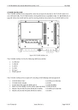
n the LT-3140S Interface Unit is hided below a cover and illustrated in Figure 30
on page 28.
NOTE
:
The input voltage range is: 12 - 24 VDC. The LT-3140S Interface Unit DC input connector
and circuit is protected and certified for Reverse Polarity Protection.
Chassis ground
The chassis ground connector is placed underneath the front cover of the LT-3140S Interface Unit and
marked with
‘GNDC’, see
WARNING
:
Only DC input power: 12 to 24 VDC must be applied on the LT-3140S Interface Unit. Crimp
tubes on the DC power cable must be used.

