5-3 BRAKES
For maintenance procedures, see
Section 4-8.
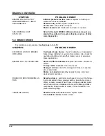
SYMPTOM
PROBLEM: REMEDY
NO BRAKES OR BRAKES
ARE INTERMITTENT
Brake air system improperly connected:
reconnect hand
valves properly.
Relay/Emergency valve plugged:
clean valve.
Defective tractor protection valve:
repair or replace.
Restricted tubing or hose line:
locate and eliminate restric-
tion.
Broken line:
locate break and repair.
Tractor air system failure:
troubleshoot tractor air system and re-
pair. Check ABS system function.
SINGLE BRAKE DRAGGING
OR LOCKED
Broken internal brake component:
locate and replace broken
part.
Flat spot on cam roller or cam shaft:
replace and lubricate.
Improper adjustment:
adjust slack adjusters.
Spider bushing or cam bracket bushing binding:
lubricate or
replace bushing.
Improper lubrication:
lubricate per
Figure 4-1.
Worn brake shoe bushing:
replace bushing.
Brake drum distortion:
replace drum.
Broken brake chamber spring:
replace spring.
Brake chamber pushrod binding:
re-align brake chamber
bracket.
Air brake line loose or broken:
tighten or repair.
UNEVEN BRAKES
See “SINGLE BRAKE DRAGGING OR LOCKED”
Restriction in hose:
locate restriction and remove.
Worn brake linings:
reline brakes.
Grease on linings:
reline brakes.
Broken slack adjuster:
replace slack adjuster.
Leaking brake chamber diaphragm:
replace diaphragm.
BRAKES APPLY TOO SLOWLY
Brakes need adjusting or lubrication:
adjust or lubricate as
needed.
Low air pressure in brake system (below 105 PSI):
check
tractor air system.
Restricted tubing or hose:
locate restriction and remove.
Defective relay valve:
clean or replace.
Call Factory or see qualified Trailer/Brake Technician
BRAKES RELEASE TOO SLOWLY
Brakes need adjusting or lubrication:
adjust or lubricate as
needed.
Brake rigging binding:
align brakes or replace bent parts.
Exhaust port of relay valve restricted or plugged:
clean
valve.
Tractor pressure too low:
Adjust to provide 105 psi min.
5-4
Summary of Contents for 600B Series
Page 8: ......
Page 12: ......
Page 14: ...3 2 Figure 3 1 Front Trailer Terminology Figure 3 2 Rear Trailer Terminology...
Page 18: ...3 6 Figure 3 4 Hydraulic Controls...
Page 26: ...3 14 Figure 3 7 Steps for Loading and Unloading...
Page 32: ...3 20 Figure 3 10 Dock Leveler Operation...
Page 38: ...3 26 Figure 3 14 Rear Impact Guard and Antilock Brake System...
Page 42: ...4 2 Figure 4 1 Lubrication Points...
Page 48: ...4 8 Figure 4 3 600B Wiring Diagram...
Page 49: ...4 9 Figure 4 4 Remote Wiring Diagram...
Page 52: ...4 12 Figure 4 5 Tandem Axle Air Ride Suspension System Figure 4 6 Air Ride Height Adjustment...
Page 54: ...4 14 Figure 4 7 Triple Axle Air Ride Suspension System...
Page 57: ...4 17 Figure 4 9 Checking Axle Alignment Figure 4 10 Examples of Camber...
Page 61: ...4 21 Figure 4 13 Axle and Brake Assembly...
Page 71: ...4 31 Figure 4 21 Dock Leveler Leg Assembly...
Page 73: ...4 33 Figure 4 22 Crank Landing Gear Assembly...
Page 84: ...NOTES 5 10...


