


4-8.2
Spring Air Brake Chambers
Check for faulty units. Check the condensation
holes on the underside of the brake chambers to
make sure they are open. The spring brake has
two brake chambers, a service chamber and an
emergency chamber or spring chamber. Service
brake chambers should be disassembled and
cleaned at 50,000 miles or yearly. The diaphragm
and any marginal parts should be replaced. When
replacing the service diaphragm, replace the corre-
sponding parts for the other chamber on the same
axle (to aid in even brake application and release).
Examine yoke pin for wear and replace as neces-
sary. The spring chamber should not be serviced.
Replace entire unit (both service and spring cham-
ber) if spring chamber becomes faulty.
WARNING
THE SPRING BRAKE CHAMBER EM-
PLOYS A SPRING WITH HIGH FORCES.
SERVICE SHOULD NOT BE AT-
TEMPTED. SERIOUS INJURY OR
DEATH MAY RESULT.
a. Caging the Power Spring
1.
Chock the trailer wheels.
2.
Remove dust cap from spring brake
chamber.
3.
Remove the release bolt from it’s holding
brackets and insert it into the spring brake
chamber. DO NOT USE AN IMPACT
WRENCH TO CAGE THE SPRING
BRAKE.
4.
Turn the bolt until the spring brake is
caged. This should be 2-1/4 to 2-1/2 inches
of release bolt extension.
5.
The brakes should now be totally released.
Do not operate loaded trailer with brake
manually released.
6.
To reset the spring brake, turn the release
bolt until the spring is released. Remove
the release bolt and store it in its brackets.
7.
Snap the dust cap back in place on the
chamber.
b. Removal
1.
Chock all tractor and trailer wheels and
drain the air system.
2.
Mark the brake chamber for proper air line
port alignment for reassembly.
3.
CAGE THE POWER SPRING following the
steps outlined in
Section 4-8.2a.
4.
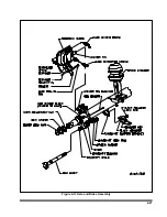
Disconnect the slack adjuster from the
connecting rod by removing the clevis pin
(See Figure 4-14)
.
5.
Mark all air service lines for proper
reinstallation and disconnect from the
brake chamber.
6.
Remove the brake chamber from the axle
brackets.
c. Installation
1.
CAGE THE POWER SPRING following the
steps outlined in
Section 4-8.2a.
2.
Position the inlet ports by loosening the
service chamber clamp bands and rotating
center housing such that ports are located
according to alignment marks made during
disassembly, then retighten the clamp
bands.
3.
Position the breather hole in the downward
facing position by loosening the clamp
bands on the spring brake chamber and
rotating the chamber housing until the
breather hold faces downward. Retighten
the clamp bands.
4.
Remount the brake chamber on the axle
brackets and reconnect the air service
hoses and the slack adjuster connecting
rod
(See Figure 4-14).
IMPORTANT
BE SURE THE SERVICE LINE ON THE
SERVICE CHAMBER PORT AND THE EMER-
GENCY LINE IS ON THE SPRING BRAKE PORT.
5.
Check for leakage by charging the air
system to a minimum of 90 psi and
applying soap suds to the brake chamber
and connections. If a growing bubble is
detected or bubbles are blown away, locate
the source of the leak and repair.
6.
Insure that the clamp band is properly
seated and tight
before
uncaging the
power spring.
4-19
Summary of Contents for 600B Series
Page 8: ......
Page 12: ......
Page 14: ...3 2 Figure 3 1 Front Trailer Terminology Figure 3 2 Rear Trailer Terminology...
Page 18: ...3 6 Figure 3 4 Hydraulic Controls...
Page 26: ...3 14 Figure 3 7 Steps for Loading and Unloading...
Page 32: ...3 20 Figure 3 10 Dock Leveler Operation...
Page 38: ...3 26 Figure 3 14 Rear Impact Guard and Antilock Brake System...
Page 42: ...4 2 Figure 4 1 Lubrication Points...
Page 48: ...4 8 Figure 4 3 600B Wiring Diagram...
Page 49: ...4 9 Figure 4 4 Remote Wiring Diagram...
Page 52: ...4 12 Figure 4 5 Tandem Axle Air Ride Suspension System Figure 4 6 Air Ride Height Adjustment...
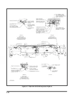
Page 54: ...4 14 Figure 4 7 Triple Axle Air Ride Suspension System...
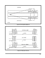
Page 57: ...4 17 Figure 4 9 Checking Axle Alignment Figure 4 10 Examples of Camber...
Page 61: ...4 21 Figure 4 13 Axle and Brake Assembly...
Page 71: ...4 31 Figure 4 21 Dock Leveler Leg Assembly...
Page 73: ...4 33 Figure 4 22 Crank Landing Gear Assembly...
Page 84: ...NOTES 5 10...


