


3
OPERATING INSTRUCTIONS
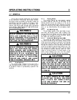
3-1 GENERAL
This section supplies information for operation
of the semitrailer. It describes and locates controls
and gives general operation procedures. Read all
instructions, warnings, cautions, and danger notes
before attempting to operate the semitrailer. Op-
erators must have proper training before operating
the semitrailer.
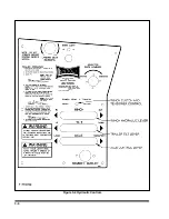
(See Figures 3-1 and 3-2 for loca-
tion of semitrailer parts.)
WARNING
DO NOT OPERATE THE SEMITRAILER
WITH ANY KNOWN FAULT THAT
MIGHT ENDANGER THE OCCUPANTS,
NEARBY WORKERS, OTHER TRAFFIC,
THE LOAD, OR THE EQUIPMENT.
WARNING
DO NOT OPERATE THE SEMITRAILER
UNTIL YOU HAVE READ THE OPERA-
TOR’S MANUAL AND COMPLETELY
UNDERSTAND THE PROPER USE AND
FUNCTION OF ALL CONTROLS. IM-
PROPER USE CAN CAUSE PERSONAL
INJURY, DAMAGE TO YOUR SEMI-
TRAILER AND CARGO, AND CAUSE
TIME-CONSUMING BREAKDOWNS.
3-1.1
Landing Gear
The landing gear consists of two legs with a
tube telescoping within another tube. Pin drop style
is standard. Crank or hydraulically operated are
optional.
3-1.2
Parking Brake
The parking brakes are automatically applied
by spring pressure with the air actuators of the
braking system when air pressure in the emer-
gency line drops below 50 psi. This may be done
within the truck using the trailer parking/emergency
valve or by disconnecting the emergency glad-
hands.
3-1.3
Air Brake System
The air brake system of the semitrailer is oper-
ated from the towing vehicle after coupling. The
towing vehicle’s air system must be coupled to the
semitrailer and charged to 90 psi minimum before
the brakes can adequately function.
3-1.4
Anti-Lock Brake System (ABS)
The Anti-Lock Brake System of the semitrailer
is constant powered by the auxiliary (blue) circuit
of the seven way electrical connector, with backup
power from the stop lamp (red) circuit, and ground
through the white wire. It is necessary that the blue
circuit is hot when the tractor key switch is on. The
blue circuit on the trailer may not be used to power
any additional auxiliary devices while the semi-
trailer is moving forward. If a fault exists in the
ABS, normal braking will occur, but the wheels
may lock. Service the ABS as soon as possible.
CAUTION
THE AUXILIARY (BLUE) CIRCUIT IS
FOR POWERING THE SEMITRAILER
ABS. THIS CIRCUIT MUST BE HOT
WHEN THE TRACTOR KEY SWITCH IS
ON. NO OTHER ELECTRICAL DEVICES
MAY BE POWERED BY THIS CIRCUIT
WHILE THE SEMITRAILER IS MOVING
FORWARD.
CAUTION
IF A FAULT EXISTS IN THE SEMI-
TRAILER ABS, NORMAL BRAKING
WILL OCCUR, BUT WHEELS MAY
LOCK AND SERVICE THE ABS AS
SOON AS POSSIBLE.
3-1
Summary of Contents for 600B Series
Page 8: ......
Page 12: ......
Page 14: ...3 2 Figure 3 1 Front Trailer Terminology Figure 3 2 Rear Trailer Terminology...
Page 18: ...3 6 Figure 3 4 Hydraulic Controls...
Page 26: ...3 14 Figure 3 7 Steps for Loading and Unloading...
Page 32: ...3 20 Figure 3 10 Dock Leveler Operation...
Page 38: ...3 26 Figure 3 14 Rear Impact Guard and Antilock Brake System...
Page 42: ...4 2 Figure 4 1 Lubrication Points...
Page 48: ...4 8 Figure 4 3 600B Wiring Diagram...
Page 49: ...4 9 Figure 4 4 Remote Wiring Diagram...
Page 52: ...4 12 Figure 4 5 Tandem Axle Air Ride Suspension System Figure 4 6 Air Ride Height Adjustment...
Page 54: ...4 14 Figure 4 7 Triple Axle Air Ride Suspension System...
Page 57: ...4 17 Figure 4 9 Checking Axle Alignment Figure 4 10 Examples of Camber...
Page 61: ...4 21 Figure 4 13 Axle and Brake Assembly...
Page 71: ...4 31 Figure 4 21 Dock Leveler Leg Assembly...
Page 73: ...4 33 Figure 4 22 Crank Landing Gear Assembly...
Page 84: ...NOTES 5 10...


