


3-18 HYDRAULIC POWER SUPPLY ENGINE OPERATION (OPTION)
3-18.1
The Hydraulic Power Supply Engine
system is used to power the hydraulic func-
tions, should the tractor not be equipped with
hydraulic hookups.
IMPORTANT
1. CHECK THE FOLLOWING FLUIDS BEFORE
STARTING THE ENGINE PACKAGE: ENGINE
OIL, FUEL SUPPLY, HYDRAULIC OIL. (CHECK
OIL LEVEL WHILE SEMITRAILER IS NOT
TILTED WILL CHANGE THE OIL LEVEL IN THE
TANK.)
2. IF THE ENGINE DOES NOT CRANK, CHECK
THE FOLLOWING ON THE BATTERY: CHARGE
FLUID, TERMINALS, AND CABLES. TAKE COR-
RECTIVE ACTIONS AS NEEDED.
CAUTION
IF THE HYDRAULIC FLUID LEVEL IS
LOW DURING OPERATION, THE SEMI-
TRAILER MAY NOT OPERATE COR-
RECTLY, RESULTING IN DAMAGE TO
THE SEMITRAILER.
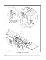
3-18.2
The
ENGINE IGNITION SWITCH
is lo-
cated on the engine control panel on the
driver’s side of the semitrailer. Use the key
to start and stop the Hydraulic Power Supply
Engine.
(See Figure 3-11).
This switch has
three positions:
OFF
In this position, the power package
engine does not run. The key can
only be inserted or removed from
this position.
RUN
In this position, the engine runs with-
out activating the starter.
START
In this position, the starter cranks the
power package engine, to start it. Af-
ter the engine is started, release the
key to the RUN position.
3-22
Figure 3-11 Engine Control Panel
Summary of Contents for 600B Series
Page 8: ......
Page 12: ......
Page 14: ...3 2 Figure 3 1 Front Trailer Terminology Figure 3 2 Rear Trailer Terminology...
Page 18: ...3 6 Figure 3 4 Hydraulic Controls...
Page 26: ...3 14 Figure 3 7 Steps for Loading and Unloading...
Page 32: ...3 20 Figure 3 10 Dock Leveler Operation...
Page 38: ...3 26 Figure 3 14 Rear Impact Guard and Antilock Brake System...
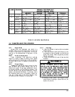
Page 42: ...4 2 Figure 4 1 Lubrication Points...
Page 48: ...4 8 Figure 4 3 600B Wiring Diagram...
Page 49: ...4 9 Figure 4 4 Remote Wiring Diagram...
Page 52: ...4 12 Figure 4 5 Tandem Axle Air Ride Suspension System Figure 4 6 Air Ride Height Adjustment...
Page 54: ...4 14 Figure 4 7 Triple Axle Air Ride Suspension System...
Page 57: ...4 17 Figure 4 9 Checking Axle Alignment Figure 4 10 Examples of Camber...
Page 61: ...4 21 Figure 4 13 Axle and Brake Assembly...
Page 71: ...4 31 Figure 4 21 Dock Leveler Leg Assembly...
Page 73: ...4 33 Figure 4 22 Crank Landing Gear Assembly...
Page 84: ...NOTES 5 10...


