


4-13.4
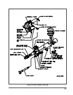
Leg (See Figure 4-21)
a.
To remove leg from trailer, disconnect the
hydraulic supply at the front of the trailer.
b.
Disconnect the hoses from the leg.
c.
To disassemble leg, first remove the check
valve assembly. Remove o-rings and back-up
washer. Using a snap ring pliers, remove
snap ring. Loosen hex screw.
d.
Lift well tube off lower leg assembly. Lift pis-
ton rod to gain access to top of cylinder.
e.
Remove four hex screws. Lift cylinder head
retainer. A wire or rubber band may be used
to hold to sprocket screwdriver, carefully re-
move spiral retaining ring. Lift piston rod as-
sembly out of cylinder tube. Using a large
snap ring pliers, remove heavy duty snap
ring. Pull off piston, cylinder head, retaining
ring and cylinder head retainer.
f.
Before reassembling leg, remove all seals
and wear rings. Clean all parts. Inspect all
bearing surfaces and sealing surfaces for
scratches, nicks or other defects, replace if
necessary. Replace all wear rings and lightly
lubricate all seals before reassembly. Care-
fully reassemble the leg reversing the order
described above.
g.
Return leg to trailer and reconnect all hoses.
Apply grease to grease fitting and cycle legs
fully several times to bleed air from system.
Check oil level.
4-14 CRANK LANDING GEAR
4-14.1
It may be necessary to periodically lu-
bricate to maintain satisfactory performance.
a.
Lube both legs through grease fittings pro-
vided in the legs two times a year or as re-
quired.
b.
Lube two-speed gears through the grease
fitting in the gearbox two times a year or as
required.
4-14.2
Gearbox Dismantling (See Figure
a.
Remove all rust from shafts and lubricate for
easier removal of gearbox cover.
b.
Remove gearbox cover by removing bolts
and nuts.
c.
To remove shaft, shaft must be free of rust.
Lubricate and tap out from mounting bracket
side. Remove shifter gear by removing spiral
pin and pin. Also remove shifter spring after
shaft has been removed.
d.
Remove shaft and step gear.
e.
Remove all worn, bent, or broken parts.
4-14.3
Leg Dismantling
a.
Disconnect cross shaft by removing nuts
and bolts and remove the landing gear from
the trailer.
b.
Remove all rust from projecting end of shaft
and lubricate for easy removal.
c.
Remove screws, leg cover, and gasket.
d.
Tap out groove pin from bevel pinion gear.
e.
Remove shaft from landing gear making
sure not to lose shims or location of shims.
f.
Next, remove nut from top of elevating
screw and inner leg assembly.
g.
Remove bevel gear from screw in inner leg
assembly.
h.
Tap end of screw with wood block or brass
hammer until screw and inner leg assembly
drop out. (Be careful not to damage screw
threads.)
4-32
Summary of Contents for 600B Series
Page 8: ......
Page 12: ......
Page 14: ...3 2 Figure 3 1 Front Trailer Terminology Figure 3 2 Rear Trailer Terminology...
Page 18: ...3 6 Figure 3 4 Hydraulic Controls...
Page 26: ...3 14 Figure 3 7 Steps for Loading and Unloading...
Page 32: ...3 20 Figure 3 10 Dock Leveler Operation...
Page 38: ...3 26 Figure 3 14 Rear Impact Guard and Antilock Brake System...
Page 42: ...4 2 Figure 4 1 Lubrication Points...
Page 48: ...4 8 Figure 4 3 600B Wiring Diagram...
Page 49: ...4 9 Figure 4 4 Remote Wiring Diagram...
Page 52: ...4 12 Figure 4 5 Tandem Axle Air Ride Suspension System Figure 4 6 Air Ride Height Adjustment...
Page 54: ...4 14 Figure 4 7 Triple Axle Air Ride Suspension System...
Page 57: ...4 17 Figure 4 9 Checking Axle Alignment Figure 4 10 Examples of Camber...
Page 61: ...4 21 Figure 4 13 Axle and Brake Assembly...
Page 71: ...4 31 Figure 4 21 Dock Leveler Leg Assembly...
Page 73: ...4 33 Figure 4 22 Crank Landing Gear Assembly...
Page 84: ...NOTES 5 10...


