


4-4
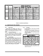
NORMAL OPERATING SERVICE INTERVALS
a
SERVICE
INTERVAL :
ITEM
TIMES
1st 5
Hrs
Weekly Monthly
6
Months
Yearly
LUBE
#
NOTES
MILES
50
500
2,000 12,000 25,000
LIGHTS
I
I
WIRING & CONNECTIONS
I
I
FASTENERS
I, T
I
b
KING PIN AND PLATE
I
C,I,L
3
c
BRAKE AIR SYSTEM
I
I
I
RELAY VALVES
I, C
BRAKE ADJ & WEAR
I
I, T
d
SLACK ADJUSTERS
I
I
L
3
c
CAMSHAFT ASSYS
I
I
L
3
c
HUB OIL
I
I, L
R
5
c
WHEEL BEARINGS
I
I, T
5
c
TIRE INFLATION & WEAR
I
I
e
WHEEL LUG NUTS
I, T
I
I, T
f
SUSPENSION ALIGNMENT
I
I
AIR RIDE SUSPENSION
I,T
I,T
UNDERCARRIAGE ROLLERS
L
3
c
HYDRAULIC OIL
I
I
R
1
c
HYDRAULIC FILTER
R
R
HOSES
I
I
R
WINCH GEAR CASE
I
I
2
c
I – Inspect, R – Replace, T– Tighten/ Adjust Torque, L – Lubricate, C – Clean
NOTES:
a. Perform at the time shown. Shorten service intervals when operating in severe or dirty conditions.
b. See
Tables 2-1 and 2-2 (General and Hydraulic Fitting Torque Charts)
for correct torque.
c. See
Table 4-1 (Lube Specification Chart)
for recommended lubricant.
d. See
Section 4-8
for procedures.
e. See Serial Number Plate on the front of the semitrailer for proper inflation requirements.
f. See
Section 4-10
for procedures.
Table 4-2 600B Maintenance Schedule
(Inspect & Replace as needed)
I,
Summary of Contents for 600B Series
Page 8: ......
Page 12: ......
Page 14: ...3 2 Figure 3 1 Front Trailer Terminology Figure 3 2 Rear Trailer Terminology...
Page 18: ...3 6 Figure 3 4 Hydraulic Controls...
Page 26: ...3 14 Figure 3 7 Steps for Loading and Unloading...
Page 32: ...3 20 Figure 3 10 Dock Leveler Operation...
Page 38: ...3 26 Figure 3 14 Rear Impact Guard and Antilock Brake System...
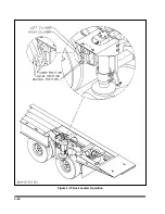
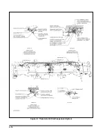
Page 42: ...4 2 Figure 4 1 Lubrication Points...
Page 48: ...4 8 Figure 4 3 600B Wiring Diagram...
Page 49: ...4 9 Figure 4 4 Remote Wiring Diagram...
Page 52: ...4 12 Figure 4 5 Tandem Axle Air Ride Suspension System Figure 4 6 Air Ride Height Adjustment...
Page 54: ...4 14 Figure 4 7 Triple Axle Air Ride Suspension System...
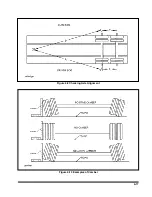
Page 57: ...4 17 Figure 4 9 Checking Axle Alignment Figure 4 10 Examples of Camber...
Page 61: ...4 21 Figure 4 13 Axle and Brake Assembly...
Page 71: ...4 31 Figure 4 21 Dock Leveler Leg Assembly...
Page 73: ...4 33 Figure 4 22 Crank Landing Gear Assembly...
Page 84: ...NOTES 5 10...


