


1
INTRODUCTION
This manual provides operating, servicing, and maintenance instructions, for Model 600B semitrailer,
manufactured by Landoll Corporation, Marysville, Kansas 66508.
SECTION 1
gives basic instructions on the use of this manual.
SECTION 2
gives specifications for the trailer, including measurements and component speci-
fications. A Standard Bolt Torque Table is provided to give guidelines for bolt
torques to be used when servicing this product.
SECTION 3
gives instructions for the proper operation of the equipment.
SECTION 4
gives general maintenance procedures, a maintenance schedule, and a lubrication
schedule. Improper maintenance will void your warranty.
IF YOU HAVE ANY QUESTIONS CONTACT:
LANDOLL CORPORATION
1900 NORTH STREET
MARYSVILLE, KANSAS 66508
or phone:
(785) 562-5381 or
(800) 428-5655
or FAX:
(785) 562-4893
SECTION 5
is a troubleshooting guide to aid in diagnosing and solving problems with the
trailer.
PARTS LIST
is a separate manual showing the various assemblies, subassemblies, and sys-
tems. Refer to that manual when ordering Landoll replacement parts. Order parts
from your Landoll dealer.
WARRANTY
The Warranty Registration form is located with the product documents. Fill it out
and mail it within 15 days of purchase. The Warranty is printed inside the front
cover.
NOTE: IMPROPER ASSEMBLY, MODIFICATION, OR MAINTENANCE OF YOUR
LANDOLL MACHINE CAN VOID YOUR WARRANTY.
COMMENTS
Address comments or questions regarding this publication to:
LANDOLL CORPORATION
1900 NORTH STREET
MARYSVILLE, KANSAS 66508
ATTENTION: PUBLICATIONS - DEPT. 55
1-1
Summary of Contents for 600B Series
Page 8: ......
Page 12: ......
Page 14: ...3 2 Figure 3 1 Front Trailer Terminology Figure 3 2 Rear Trailer Terminology...
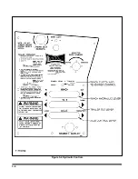
Page 18: ...3 6 Figure 3 4 Hydraulic Controls...
Page 26: ...3 14 Figure 3 7 Steps for Loading and Unloading...
Page 32: ...3 20 Figure 3 10 Dock Leveler Operation...
Page 38: ...3 26 Figure 3 14 Rear Impact Guard and Antilock Brake System...
Page 42: ...4 2 Figure 4 1 Lubrication Points...
Page 48: ...4 8 Figure 4 3 600B Wiring Diagram...
Page 49: ...4 9 Figure 4 4 Remote Wiring Diagram...
Page 52: ...4 12 Figure 4 5 Tandem Axle Air Ride Suspension System Figure 4 6 Air Ride Height Adjustment...
Page 54: ...4 14 Figure 4 7 Triple Axle Air Ride Suspension System...
Page 57: ...4 17 Figure 4 9 Checking Axle Alignment Figure 4 10 Examples of Camber...
Page 61: ...4 21 Figure 4 13 Axle and Brake Assembly...
Page 71: ...4 31 Figure 4 21 Dock Leveler Leg Assembly...
Page 73: ...4 33 Figure 4 22 Crank Landing Gear Assembly...
Page 84: ...NOTES 5 10...


