


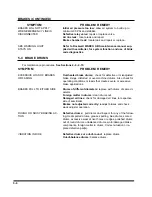


TIRES - WHEELS - SUSPENSION (CONTINUED)
SYMPTOMS
PROBLEM: REMEDY
RIM FAILURE*:
CRACKING
Overinflated tires:
deflate tire to proper PSI.
High speeds:
adjust speed according to road and load condi-
tions.
High speed cornering:
adjust cornering practices.
Over loading:
check rim load rating.
*IN ALL INSTANCES OF RIM FAILURE, REPLACE THE RIM IMMEDIATELY!
BENDING OR WARPING
Curb-hopping or potholes:
adjust turning practices and adjust
speed accordingly with road conditions.
Improper tightening sequence:
follow proper tightening se-
quence. (
See Figure 4-20)
BROKEN STUDS*
Over tightening:
use correct torque when mounting.
*REPLACE BROKEN STUDS BEFORE USING THE SEMITRAILER!
SEMITRAILER TRACKING PROB-
LEMS:
TRACKS TO ONE SIDE
Axle alignment:
re-align axle.
TRACKS TO EITHER SIDE
Broken or bent springs or equalizers:
replace defective
parts.
Axles not parallel
: realign axles
AIR RIDE HEIGHT PROBLEMS:
TOO HIGH
Axle to control valve linkage:
readjust linkage.
Height Control Valve internal leak:
repair or replace valve.
TOO LOW
Axle to control valve linkage:
readjust linkage.
Height Control Valve filter plugged:
clean or replace valve.
Pressure Protection Valve filter plugged:
clean or replace
valve.
System air pressure low (65 PSI minimum required):
trou-
bleshoot air supply.
UNEVEN FROM SIDE TO SIDE
Linkage adjustment:
readjust linkage.
Exhaust port plugged:
clean or replace valve(s).
Height control valve internal leak:
repair or replace valve.
Supply line to one height control valve pinched, restricted,
or plugged:
repair or replace line.
5-3
Summary of Contents for 600B Series
Page 8: ......
Page 12: ......
Page 14: ...3 2 Figure 3 1 Front Trailer Terminology Figure 3 2 Rear Trailer Terminology...
Page 18: ...3 6 Figure 3 4 Hydraulic Controls...
Page 26: ...3 14 Figure 3 7 Steps for Loading and Unloading...
Page 32: ...3 20 Figure 3 10 Dock Leveler Operation...
Page 38: ...3 26 Figure 3 14 Rear Impact Guard and Antilock Brake System...
Page 42: ...4 2 Figure 4 1 Lubrication Points...
Page 48: ...4 8 Figure 4 3 600B Wiring Diagram...
Page 49: ...4 9 Figure 4 4 Remote Wiring Diagram...
Page 52: ...4 12 Figure 4 5 Tandem Axle Air Ride Suspension System Figure 4 6 Air Ride Height Adjustment...
Page 54: ...4 14 Figure 4 7 Triple Axle Air Ride Suspension System...
Page 57: ...4 17 Figure 4 9 Checking Axle Alignment Figure 4 10 Examples of Camber...
Page 61: ...4 21 Figure 4 13 Axle and Brake Assembly...
Page 71: ...4 31 Figure 4 21 Dock Leveler Leg Assembly...
Page 73: ...4 33 Figure 4 22 Crank Landing Gear Assembly...
Page 84: ...NOTES 5 10...


