


3-5 TRACTOR AND SEMITRAILER CHECK-OUT
WARNING
FAILURE TO PROPERLY SET AND
CHECK PARKING BRAKE, AND
CHOCK WHEELS WHEN PARKING
AND DURING STORAGE, COULD AL-
LOW
MOVEMENT
OF
THE
TRUCK/SEMITRAILER RIG RESULT-
ING IN SERIOUS PERSONAL INJURY,
DEATH, OR DAMAGE TO PROPERTY
IN ITS PATH.
3-5.1
With hydraulic power operating, raise
landing gear:
a.
For pin drop landing gear, activate the
TRAILER TILT
lever “UP”
(See Figure 3-4)
until weight is off the landing gear. Raise
landing gear.
(See Section 3-9 for operation
of TRAILER TILT lever.)
Secure each leg
with a park stand retaining pin in the full “up”
position before transporting.
CAUTION
ALWAYS GRIP CRANK HANDLE SE-
CURELY WITH BOTH HANDS. NEVER
SHIFT LANDING GEAR UNDER LOAD,
LEAVE THE GEARS IN NEUTRAL OR
LEAVE THE CRANK UNSECURED.
b.
For crank landing gear, retract landing gear
by turning hand crank on control panel coun-
terclockwise. Use low gear until the load is off
the landing gear. Then shift to high gear and
continue cranking until fully retracted. Leave
the landing gear in high gear.
c.
For hydraulic landing gear, remove the pin
from each landing gear leg. Retract landing
gear using lever
(See Section 3-5.2)
on en-
gine control panel
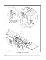
(See Figure 3-11)
. Secure
each leg with a pin in fully retracted position.
3-5.2
The
LANDING GEAR lever
is located
on the left side of the Engine Control Panel.
It has three positions:
RETRACT
In this position, the landing gear are
pulled up off the ground.
CENTER
This is neutral position.
EXTEND
In this position, the landing gear are
lowered to the ground.
CAUTION
1. LANDING GEAR LEGS MUST BE
FULLY RETRACTED AND SECURED
WITH PINS BEFORE OPERATING OR
MOVING SEMITRAILER.
2. IF SEMITRAILER IS LOADED WHEN
OPERATING LANDING GEAR, LOAD
MUST BE CENTERED ON THE
TRAILER.
3. DO NOT TILT SEMITRAILER WITH
HYDRAULIC LANDING GEAR ON
GROUND.
3-5.3
Activate the
TRAILER TILT lever (See
Section 3-9)
“DOWN” until the semitrailer is
fully lowered. Hold semitrailer tilt lever in the
down position until hydraulic system works
against the bottomed out Hydraulic Tilt Cylin-
ders.
3-5.4
Determine that the traveling undercar-
riage is completely slid back to transport po-
sition. Hold
AXLE CONTROL lever (See
Section 3-10)
in the transport position until
hydraulic system works against the fully ex-
tended hydraulic telescopic axle cylinder.
Shut off hydraulic power.
3-5.5
Check the operation of all lights and sig-
nals on the semitrailer for proper response to
switch positions (stop, right turn, left turn,
and clearance). Check operation of remote
function if present.
3-5
Summary of Contents for 600B Series
Page 8: ......
Page 12: ......
Page 14: ...3 2 Figure 3 1 Front Trailer Terminology Figure 3 2 Rear Trailer Terminology...
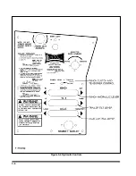
Page 18: ...3 6 Figure 3 4 Hydraulic Controls...
Page 26: ...3 14 Figure 3 7 Steps for Loading and Unloading...
Page 32: ...3 20 Figure 3 10 Dock Leveler Operation...
Page 38: ...3 26 Figure 3 14 Rear Impact Guard and Antilock Brake System...
Page 42: ...4 2 Figure 4 1 Lubrication Points...
Page 48: ...4 8 Figure 4 3 600B Wiring Diagram...
Page 49: ...4 9 Figure 4 4 Remote Wiring Diagram...
Page 52: ...4 12 Figure 4 5 Tandem Axle Air Ride Suspension System Figure 4 6 Air Ride Height Adjustment...
Page 54: ...4 14 Figure 4 7 Triple Axle Air Ride Suspension System...
Page 57: ...4 17 Figure 4 9 Checking Axle Alignment Figure 4 10 Examples of Camber...
Page 61: ...4 21 Figure 4 13 Axle and Brake Assembly...
Page 71: ...4 31 Figure 4 21 Dock Leveler Leg Assembly...
Page 73: ...4 33 Figure 4 22 Crank Landing Gear Assembly...
Page 84: ...NOTES 5 10...


