


45
APPENDIX 3. PROGRAMMING EXAMPLE
This example is based on the LabSmith application note entitled,
Microfluidics with the LabSmith LabPackage: Making a
Microfluidic Injection on a Chip
.
One of the most important advantages of microfluidic channels on planar substrates is the ability to use electric fields to confine
volumes without creating dead volumes or carry over. Described here are the steps and requirements to perform a so-called
“pinched injection” (Jacobson, S. C.; Hergenroder, R.; Koutny, L. B.; Warmack, R. J.; Ramsey, J. M.
Anal. Chem.
1994, 66, 1107-
1113).
In the pinched injection the load step uses applied voltages at all four reservoirs to define a time-independent volume between
the sample (A) and sample waste (C) reservoirs. An inject step applies a different voltage sequence to pull back the sample and
sample waste fluid while sweeping the defined injection plug from buffer to buffer waste.
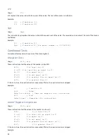
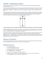
Figure 31
shows a diagram of a
generic microfluidic chip. This example assumes the use of a standard Caliper NS12A chip.
Figure 31. Diagram of basic cross microfluidic chip. Reservoir Guide: A=Sample; B=Buffer waste; C= Sample waste; D=Buffer
The HVS448 High Voltage sequencer will control the electric fields to perform a two-step automated sequence. In the first step,
“LOAD,” the voltages will control a flow from reservoir A to reservoir C. Voltages applied to B and D will be used to “pinch” the
flow at the intersection and define a time-independent sample plug size.
In the second step, “INJECT,” the largest voltage drop will be from reservoir B to reservoir D, with smaller voltages at A and C to
pull back the volumes in the sample channel. This will sweep the injection plug defined in the LOAD step into the longer
separation channel. In this example there is only one component; however, in a typical electrophoretic separation there would
be multiple components. The practical aspects of detection are not discussed in this example. Four of the eight channels on the
HVS448 will be used to perform this experiment.
Setting up the Experiment
Prior to programming the Sequence the channels would need to be prepared, reservoirs placed and filled, and electrodes from
Channels A-D applied to the four reservoirs per the instructions in the application note.
Writing the Sequence
1.
Launch Sequence software.
2.
Choose
Tools>Simple Sequence Wizard
.
3.
On the
Step A
tab change the Step name to “Loading.”
4.
Set the
Switch Step
setting to
Only Manually
.
5.
Now set Channels A-D to regulate D.C. voltages, according to
6.
Table
4
.
You can either click and drag the DC Voltage sliders to set the values, or enter the values directly
in the
DC Voltage
boxes.
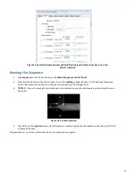
Figure 32
shows these settings applied.
A
B
C
D


