LabSmith HVS448 User Manual Download Page 22


22 

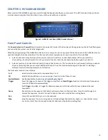
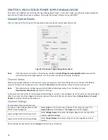
CHAPTER 6. HIGH VOLT

AGE SEQUENCING: AUTOMATED MODE 

As you have seen, the HVS can function as an eight-channel, high voltage power supply and sensor. You can set its channels 
manually and monitor the results of those changes. 

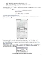
The next step is to automate the channel settings with the HVS’s sequencing environment, which gives you the ability to execute 
coordinated, non-trivial programs at high speed. Automation is accomplished through “sequences.” A Sequence is a set of 
automated commands grouped into 

Programs

. Programs consist of individual 

Instructions

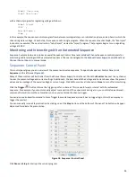
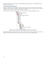
In automated mode you will typically perform the following steps: 

-


In Sequence™, program the sequence steps and settings for each channel. 

-


Store those properties and logic to the HVS448’s memory. 

-


Test your sequence by manually issuing control commands and examining the channel states, using the software, the 
HVS448’s channel LEDs and/or a multimeter.  

-


Connect your experimental equipment to the HVS448. 

-


Run the experiment, using the HVS448 by itself or with the computer.  

Appendix 2.

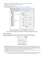
 HVS448 System Architecture  includes a diagram that shows the overall HVS448 system architecture. 

Master and Channel Sequencers 

The highest authority in this architecture is the 

Master Sequencer

. It coordinates the functions of the eight

 Channel Sequencers 

(A –H), which control and monitor the high voltage inputs/outputs. Unlike the channels, the Master does not control a high 
voltage output, nor does it trigger inputs and outputs. 

The Master and Channels execute independent 

Sequences

 in parallel.  

While the Master and Channels run independent sequences, they can also communicate via three methods: 

-


Step instructions

 let all channels jump simultaneously to defined points in their sequences 

-


Flags

, which are variables that can be set, cleared and/or read by any channels 

-


Trigger signals

, which let a particular channel respond to a combination of internal or external events. 

Manual Changes During an Automated Sequence 

When you run a sequence, the Sequence software will automatically change channel functions and settings. At the same time, 
you can continue to make manual changes through the 

Channel Control Panels

 and 

Manual Power Supply Control Panel

. You 

many need to do this, for example, if you want an event to occur when Channel A reaches some yet-unknown voltage level. The 
HVS gives you the ability to manually adjust that voltage at the appropriate time so that you can determine that unknown level.  

Once you start running a sequence, the channel states will change automatically.  

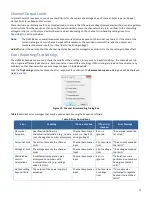
Inter-Channel Communication 

In all but the simplest sequences, the channels must be able to influence each other, for example, to signal an over-current 
condition or to move to a new step in the sequence. There are three mechanisms of inter-channel communications: step 
instructions, flags, and triggers. 

Use 

Step

 instructions to switch between conceptual portions of a sequence, when multiple channels must react simultaneously. 

Use 

Flags

 for general purpose signaling among channels. Flags can be assigned different meanings by the user at different times 

within a step. 

Use 

Triggers

 to communicate with external equipment, to create “protected” communication pathways between channels, and 

to facilitate complicated signaling logic. Trigger logic can be different for different steps, but is constant during a step.  
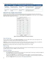
Step Instructions 

Step instructions are interrupts which force the master and channel sequences to jump from their current programs to a 
prescribed one-instruction step program. Step instructions should be used where there is a clearly defined change that affects 
multiple channels—for example, switching from an “initialization” step to a “run” step. 

A one-instruction step program will include a “Continue”, “Run” or “Exit” instruction. 

A “Continue” instruction resumes the program that was running before the Step instruction.  

Summary of Contents for HVS448

Page 1: ...LabSmith HVS448 High Voltage Sequencer User Guide Version 1 5 For operation and control of LabSmith HVS448 High Voltage Sequencer and Sequence Driver Software...

Page 2: ...duced or distributed without the consent of LabSmith LabSmith HVS448 and Sequence are trademarks of LabSmith Inc Microsoft Windows NT XP 7 and 8 are registered trademarks of Microsoft Corporation Adob...

Page 3: ...ions 14 Digital Connections 14 Recalibrating the Channels 15 CHAPTER 4 SEQUENCE SOFTWARE OVERVIEW 16 Field Upgradeable Firmware 16 Sequence Files 16 Online and Offline Operation 16 Sequence Software E...

Page 4: ...30 CHAPTER 7 CHANNEL PROGRAM INSTRUCTIONS 31 Nomenclature 31 Execution Controls 31 Inter channel Signaling and Triggering 33 Channel Functions 35 Register Functions 36 Calculator Functions 37 Reverse...

Page 5: ...igh Voltage Sequence Available Models Model Max Output Voltage V Max Voltage Differential V Max Output Current mA Max Output Current Per Channel mA Current Monitor Resolution nA Voltage Monitor Resolu...

Page 6: ...ting Help This guide is your main source for information on operating the HVS448 and Sequence software Choose Help About Sequence then click the Open User Manual link to browse this manual electronica...

Page 7: ...ttaching any one of the grounding leads to a ground source WARNING Do not handle cable terminations or clips while they are connected to an energized circuit The micro and nano clips do not protect fr...

Page 8: ...ton or choose Actions Disable High Voltage When the high voltage is disabled the LED over the ALL button will turn off or will glow red if the Interlock is not satisfied Enable High Voltage From the f...

Page 9: ...Using the Sequence Wizards to Create a Sequence File Sequence Wizards simplify the process of creating sequences by letting you enter voltages and currents directly for each step of the sequence A se...

Page 10: ...TTL signal at any of the four inputs In1 In4 5 Enter the setting changes for each channel during this step a Select Unchanged to leave the channel in the same state as the previous sequence step b Se...

Page 11: ...aveform shape you wish to apply then set Offset V the DC offset if any applied to the waveform Amplitude V the peak to peak voltage differential of the waveform Note By default generated waveforms are...

Page 12: ...VS448 now box b If the HVS448 was online prior to programming choose Actions Program All 5 In the left pane click Sequence to open the Sequencer Control Panel 6 Press A at the bottom of the Sequencer...

Page 13: ...ply that function to The function button will remain lit after you select a channel indicating that you can select additional channels Push the function button again to deselect it Selecting a differe...

Page 14: ...button glows a steady red and all buttons are dark The front panel can be unlocked by choosing Actions Unlock Front Panel This is the default condition When the panel is unlocked the power LED glows g...

Page 15: ...st 30 minutes before calibration 4 Run the Sequence software 5 In Sequence enter Online mode by clicking the toolbar button 6 Click the toolbar button to enable high voltage The All indicator on the H...

Page 16: ...rnal source is supplied then they will indicate near 0 V When you open a Sequence file the channels remain inputs Click the Update All button at the bottom of Sequence s right pane to set all of the c...

Page 17: ...asurement interval is the frequency with which measurement values are updated in milliseconds The measurement interval must be an integer in the range of 1 to 1000000000 The new measurement interval w...

Page 18: ...nd values continuously Note The default monitor setting is governed by the Monitor Settings dialog To set the default choose View Options Monitoring see Monitor Settings A channel can monitor either i...

Page 19: ...rent settings If Monitoring is turned on for a channel any problems on that channel will cause a message to appear in the Errors field Click the Trip Setting button to choose the error responses for a...

Page 20: ...current experiment The voltage and current sliders for each channel will adjust to reflect your choice Update All synchronizes the data from all channels reads the calibration data updates all channel...

Page 21: ...s settings expand the channel in the left pane Figure 17 Figure 17 Channel A s High Voltage Settings Shown in the Left Pane The function and limits from the Channel Control Panels will be displayed I...

Page 22: ...h let a particular channel respond to a combination of internal or external events Manual Changes During an Automated Sequence When you run a sequence the Sequence software will automatically change c...

Page 23: ...r step instructions until the master sequencer terminates the program by issuing its own Exit instruction see Exit If any special shutdown procedures are required by a channel they should be run in St...

Page 24: ...s not possible with flags reducing the potential for software bugs For example the earlier example of coordinating channels to make complementary square waves may be better implemented using triggers...

Page 25: ...cer Control Panel click Sequencer in the left pane Figure 18 Many of these controls will be familiar from the Manual Power Supply Control Panel Check the Monitor box next to any channel to view the pr...

Page 26: ...esh the values Check the Continuously Monitor Measurements box to update the values on a continual basis The Navigate Programs drop down menu shows the channel programs Select a program to view its co...

Page 27: ...me hierarchy as the software sequences consist of steps and programs programs consist of instructions In the left pane double click Sequencer to expand and view the master and channels controls Figure...

Page 28: ...diting a Program Instruction in the Left Pane To add a new instruction right click on an instruction within that program From the drop down menu that appears choose New Instruction A new instruction w...

Page 29: ...lbar button Figure 28 Programming Keypad To use the keypad open the text of a sequence or program in the right pane Place the cursor where you want to add a command then click the required instruction...

Page 30: ...struction will also appear in red as will the sequence containing the program and the Sequence icon itself to help you quickly spot the problem In the example in Figure 30 the same label appears twice...

Page 31: ...All program labels that start with a capital letter are globally known by all programs of the particular channel No two global labels can be the same for any of the programs of a channel Local Labels...

Page 32: ...ns between these timing commands provided it is less than the specified duration Example Do something that takes 12 5 ms 12 5 ms Pause pause until the pause counter reaches 12 5 ms execute instruction...

Page 33: ...p instruction is Continue the program will remain stopped Example Stop The program waits here for a Step change or user command Exit Usage Exit The Exit instruction takes no argument and behaves diffe...

Page 34: ...F2 F3 F4 This instruction tests whether the specified flag is clear If it is clear the next instruction is executed If it is not clear the next instruction is skipped This instruction has no other ef...

Page 35: ...cuted if it is not clear the next instruction is skipped This instruction has no other effect Example Label a InputClear Loop while the trigger input is clear Goto a Get here when the trigger input is...

Page 36: ...in RAM memory to 13 registers A M Unlike the stack which can store up to 16 numbers sequentially the registers can be accessed randomly The registers are cleared set to zeros at system startup but ar...

Page 37: ...ains 99 The X register now contains 117 The behavior of each operation on the numerical stack is detailed for each instruction Integral Representation of Real Numbers All numbers in the stack are 24 b...

Page 38: ...uA X contains 16 uA Y contains 10 s SwapXY X contains 10 s Y contains 16 uA ClearX Usage ClearX ClearX sets the X register to 0 without changing the other values in the stack Example 10 X contains 10...

Page 39: ...6 X contains 166 Y contains 10 12 X contains 12 Y contains 166 X contains 13 166 12 13 833 Y contains 10 Mod Usage Mod The instruction Mod removes the top two numbers on the stack X and Y and places t...

Page 40: ...th 0 X 0 X is less than 0 X 0 X is less than or equal to 0 X 0 X is equal to 0 X 0 X is not equal to 0 X 0 X is greater than or equal to 0 X 0 X is greater than 0 If the test is true the next instruct...

Page 41: ...41 10 X contains 10 16 X contains 16 Y contains 10 X Y False Goto Initialize Does not execute this instruction X Y True Goto Inject Executes this instruction...

Page 42: ...ce All channel states remain as they are This is equivalent to the Pause Resume button on the HVS448 front panel Resume restarts progress of the current sequence This is equivalent to the Pause Resume...

Page 43: ...programming Paste lets you paste text within your programming Help lets you access Sequence s manual Enable high voltage output allows the high voltage connectors to respond to the current settings a...

Page 44: ...BNC B OUTA BNC HVC SHV BNC G HVE SHV BNC HVD SHV BNC IN1 BNC Sequencer Channel F 1 4 Input Output High Voltage Step 1 8 OUTC BNC HVH SHV BNC Programmable Trigger Logic Inputs Outputs in1 in2 in3 in4...

Page 45: ...e In the first step LOAD the voltages will control a flow from reservoir A to reservoir C Voltages applied to B and D will be used to pinch the flow at the intersection and define a time independent s...

Page 46: ...p A Loading 7 Click on the Step B tab to view its settings 8 Change the Step B name to Injection 9 Set the Switch Step setting to Only Manually 10 Set Channels A D to regulate D C voltages according t...

Page 47: ...g voltage sequence On the Manual Sequence Control Panel you should now see channels A D maintaining the voltages from 3 Table 4 If you are viewing the microchannel on a microscope you should observe a...

Page 48: ...p 9 Noisy Channels Operating at low voltages 200 V The HVS is designed for optimal performance at high voltages Use a higher common mode voltage to achieve the desired potential difference i e apply 1...

Reviews: