


25
StepC: Continue;
StepD Continue;
…
with a channel program for regulating voltage as follows:
Label Inject
;
500V ;
Reg Voltage ;
Stop ;
In this example, the sequence controls program flow between two logical steps: an initialization phase, and a phase in which the
channel regulates voltage. At each step, the sequence calls a single program. When the sequence reaches StepB, the “Run Inject”
instruction is executed. The next instruction, “Label Inject,” names the “Inject” program. That program begins to run, regulating
voltage at 500 V.
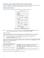
Monitoring and Interacting with an Automated Sequence
Sequence’s automated mode includes an overall Sequencer Control Panel and individual Channel Sequence control panels for
monitoring and interacting with the automated sequence. These are analogous to the
Manual Power Supply Control Panel
and
Channel Control Panels
in manual mode.
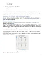
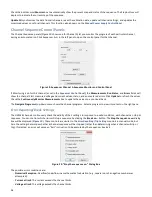
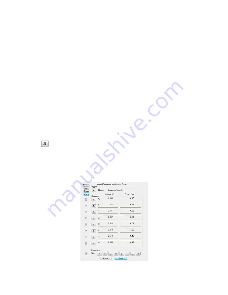
Sequencer Control Panel
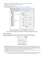
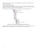
This control panel gives you an overview of the present automated sequence. To open the Sequencer Control Panel, click
Sequencer
in the left pane (
Figure 18
).
Many of these controls will be familiar from the Manual Power Supply Control Panel. Check the
Monitor
box next to any channel
to view the present voltage and current settings. Additionally, the bars beneath the Voltage and Current boxes show the present
values as a percentage of the overall voltage or current range. Click
All
to monitor all channels or
None
to turn off all monitoring.
Click the
Trigger
button to force the trigger input for a channel. This is a useful way to interact with the automated
sequence. For example, if you must manually adjust some portion of the experiment during a run, you could include an
Await
command that will resume the automated run once you’ve forced the channel trigger.
You can also use an Await command to Force Trigger the master sequence (since it has no trigger logic, this is the only way to
trigger the master).
You can manually issue a Step instruction by clicking one of the
Step
buttons at the bottom of the panel. The button will appear
depressed to indicate the present step.
Figure 18. Sequencer Control Panel
Click
Pause
or
Stop
to interrupt the current program.


