


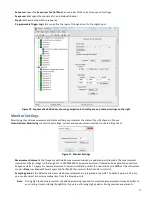


21
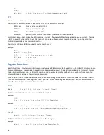
If Monitoring is on for that channel, the Current slider will adjust to reflect the present current measurement (
Figure 15
).
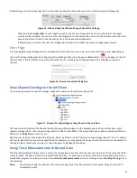
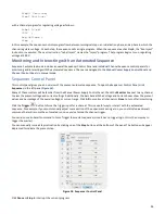
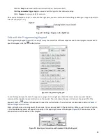
Figure 15. Click and Drag the Slider to Change Channel A’s Voltage
-
Click and drag the
right slider
to set a target current for the channel to regulate. As you move the slider, the target
current will be displayed. You can also enter the target value in the Current box. You will not be able to move the slider
beyond the Current Limits for the channel (as set in the
Channel Control Panels
).
If Monitoring is on for that channel, the voltage slider will adjust to reflect the present voltage measurement.
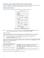
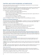
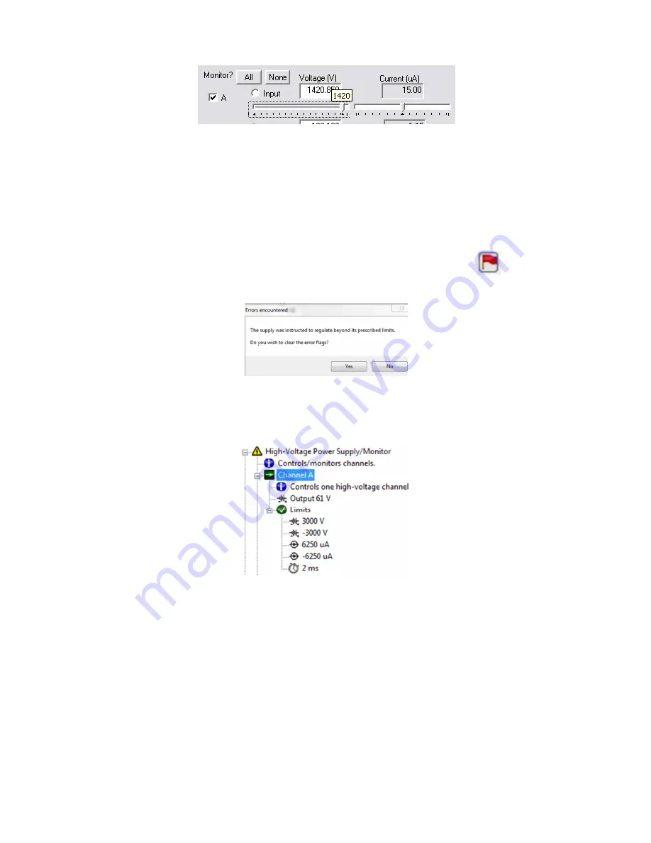
Error Flags
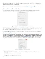
If by changing the target Voltage value you exceed the current limits (or vice versa), the channel will trip or clip, depending on
the error handling settings (See
Error Reporting/Trip Settings
). When this happens an
Error
button
will appear to the left
of the channel. Click the button to view the encountered error. A dialog box will appear (
Figure 16
). Click
Yes
to reset the
channel.
Figure 16. Errors Encountered Dialog Box
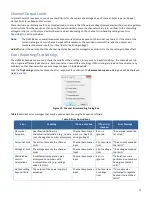
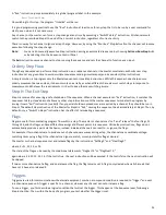
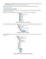
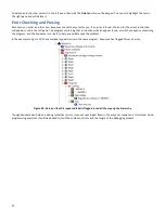
View Channel Settings in the Left Pane
For a quick overview of a channel’s settings, expand the channel in the left pane (
Figure 17
):
Figure 17. Channel A’s High Voltage Settings Shown in the Left Pane
The function and limits from the
Channel Control Panels
will be displayed. In the example above, Channel A has been set to
regulate voltage at 61 V, with lower and upper limits of 3000 V and -3000 V. The current limits have been specified at 6250 and -
6250 μA. The
Holdoff
value is set to 2 ms.
Each channel includes a text label in the left pane, which, by default, reads “Controls one high voltage channel.” You can change
this text to identify the channel more specifically; for example, you may specify the device to which the channel is connected. To
change the label, click the text to select it, then click again to highlight it for editing.
Using Trace Measurements to Record Data
The Trace Measurements option lets you record the voltage and current for each channel over a period of time, using the HVS as
a data recorder. The data is stored to a tab-delimited file, with a .trc extension by default, which can be imported directly into a
spreadsheet program for further analysis. Choose
File>Trace Measurements
to start recording; choose
File>Stop Tracing
to end
the recording.
Note
:
You should not select or deselect channel monitoring while Trace Measurements is enabled. Doing so can lead to
unexpected output.


