


14
Front Panel LEDs
The front panel LEDs provide information on the state of the channel or the unit. The channel indicators were modified in version
1.153 of the Sequence
TM
software to improve HVS448 performance.
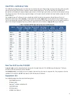
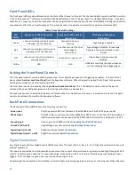
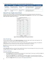
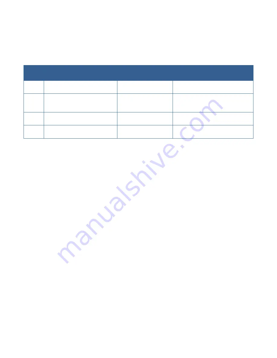
Table 1
below shows the standard LED settings. During the
execution of a sequence, the master sequencer can be programmed to override any channel or the
ALL
LED setting (however this
may adversely affect the unit performance). This would be used, for example, to indicate the execution status (see
LED
).
Table 2 Front Panel LED Settings
LED
Status
Sequence v1.152 and previous
Channel A-H
Sequence v1.153 and later
Channel A-H
All Versions of Sequence
Channel ALL
Green
channel is sinking current (current
is flowing into the channel)
channel is sinking or
sourcing
high voltage is enabled
Red
channel is sourcing current (current
is flowing out of the channel)
error has occurred (such as
overvoltage or
overcurrent)
high voltage is disabled, for example
because of an open interlock or over-
current
Off
channel is an input (not sinking or
sourcing current)
channel is an input or off
high voltage has been manually
disabled
Yellow
N/A
N/A
HVS448 is switching the high voltage on
or off or changing the voltage ranges
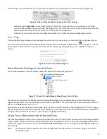
Locking the Front Panel Controls
The front panel controls can be locked to prevent users from adjusting sequences or triggering a program. To lock the front
panel, choose
Actions> Lock Front Panel
from the Sequence software.
When the panel is locked, the LED next to the power
button glows a steady red and all buttons are dark.
The front panel can be unlocked by choosing
Actions>Unlock Front Panel
. This is the default condition. When the panel is
unlocked, the power LED glows green and the front panel buttons are illuminated.
The Lock functions are nonvolatile: the panel will remain locked or unlocked even if power is removed and restored. The panel
can only be unlocked from within the Sequence software.
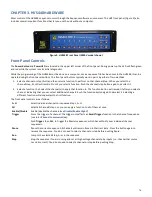
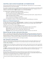
Back Panel Connections
The back panel of the HVS448 houses the following connections
Power input
Plug the power cable from the back of the HVS448 into a 90–250 VAC power outlet
RS232 socket
A RS232 cable is used to connect the HVS448 to a RS232 port on the host PC. Alternatively, a
USB-to-serial adapter can be used with the RS232 cable to connect to a USB port on the PC.
Grounding pin
Used to ground HVS448 unit (see
Grounding the HVS448 Channels
)
Channels [HVA-HVH]
High Voltage input channels (see
High Voltage Connections
)
Digital Inputs [in1-in4]
Digital Inputs (see
Digital Connections
)
Digital Outputs [outA – outD]
Digital Outputs (see
Digital Connections
)
Digital Connections
Four digital inputs and four digital outputs (BNC connectors, TTL-level, (0–0.2 V: low; 2.4–5.5 V: high) allow communication with
external equipment.
The inputs be connected to interlock switches, sensors or the outputs of other channels. Inputs are pulled high through a 20 KΩ
resistor; therefore, when open the TTL input reads high, when short-circuit it to read low. This allows passive testing of input
triggers. If a TTL voltage is applied, the input can be forced high or low.
Outputs might be connected to limit switches, indicator lights, monitoring equipment, alarms, or to the inputs of other channels.


