background image

Chapter 3: Getting Started


Product Service 1-800-522-7658 

15 

Original instructions 

b)


Electronic configuration 

 
Keypad operations are shown as 

blue bold italic

. Menu screen selections are 

shown as 

green italics

.  


1.


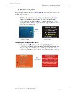
With the unit in operation, access the menu by pressing the 

Menu


button. The display panel will show the first level menu. Select 

Service

 menu by pressing the 

 or 

 buttons until the 

Service

 is 

highlighted.  Press 

OK

 to accept that option, or press 

Menu

 to return 

to the previous menu level. 


Menu 


Display Mode 


Menu Mode 

Selecting the Configuration Menu 

2.


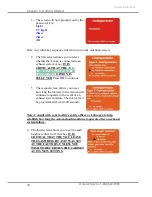
Using the 

 and 

 buttons on the touchpad, highlight the 

Configuration

 option-it will be highlighted when selected. Press 

OK


and you will get an Attention screen, advising you the following 
screens may alter the operation of the Axiom. Press 

OK

  to continue: 


OK


Summary of Contents for Purifier Axiom 30441 Series

Page 1: ...L labconco labconco com HOME PAGE www labconco com To receive important product updates complete your product registration card online at register labconco com User s Manual Purifier Biological Safety...

Page 2: ...Original instructions This page is intentionally blank...

Page 3: ...the hours of 7 30 a m and 5 30 p m Central Standard Time Part 3848320 Rev E ECO K541 Warranty Labconco Corporation provides a warranty to the original buyer for the repair or replacement of parts and...

Page 4: ...ift Base Stands 10 SoLo Electric Hydraulic Lift Base Stands 11 Preparing the Biosafety Cabinet for Operation 11 Connecting the Biosafety Cabinet to Utility Service Lines 12 Optional Exhaust Connection...

Page 5: ...nits of Measure 41 Startup Tone 42 Security Lock 42 RS 232 Output Rate 42 UV Settings 43 UV Lamp Hourmeter 43 Reset UV Lamp Hourmeter 43 Change UV Lamp Life 44 Service Menu Screens 44 Timer Operation...

Page 6: ...Data 63 Motor Specifications 63 Environmental Conditions 63 APPENDIX D ACCESSORIES 64 APPENDIX E QUICK CHART 65 CAUTION See Manual When this symbol is on the unit it indicates a caution that is detai...

Page 7: ...ease acquaint yourself with this manual and keep it handy for future reference If you are unfamiliar with how biosafety cabinets operate please review Chapter 4 Performance Features and Safety Precaut...

Page 8: ...s Service utility requirements Space requirements Refer to Appendix C Specifications for complete biosafety cabinet electrical and environmental conditions specifications and requirements Space Requir...

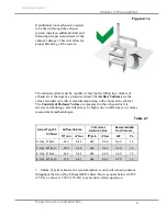
Page 9: ...windows in the room should remain closed Figure 2 1a shows the preferred location for the biosafety cabinet Air register blocked or redirected to prevent cabinet disruption Alternate location Main Dis...

Page 10: ...ort should be clear of structural elements water and utility lines or other fixed obstructions There should be enough clearance to accommodate a 10 inch diameter duct Avoid cabinet locations that requ...

Page 11: ...the cabinet The Concurrent Balance Values are measured in the exhaust duct via traverse methodology and will always be higher due to differences in volume measurement methodologies Axiom Type C1 Airf...

Page 12: ...e to the right rear side of the cabinet at a height even with or higher than the top of the bench or stand Models rated for 100 or 115 VAC will require a 20 Amp outlet Consult your local electrical co...

Page 13: ...egulator to reduce the line pressure Note The use of flammable gases or solvents should be avoided in the biosafety cabinet Open flame in the cabinet will disrupt the laminar airflow in the cabinet an...

Page 14: ...all the cabinet Connect the electrical supply source Connect the service lines Connect to an exhaust system optional Arrange certification of the biosafety cabinet Tools required for installation the...

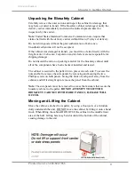
Page 15: ...Do not discard the carton or packing material for the biosafety cabinet until all of the components have been checked installed and tested The cabinet is secured to the pallet in two places on each si...

Page 16: ...e stands are included with some Axiom models or are available separately The base stands for each width cabinet are listed in Table 3 1 below An optional caster wheel kit is available part 3730500 Wid...

Page 17: ...3780331 3780335 3780339 6 3780313 3780317 3780333 3780337 3780341 Preparing the Biosafety Cabinet for Operation Installation instructions Labconco P N 1056801 are attached to the sash of the biosafet...

Page 18: ...tubing from the rear of the cabinet ensuring that it will line up with the slot in the back of the side panel The slot is located from 8 to 11 inches 222 to 288 mm from the bottom of the cabinet Note...

Page 19: ...valve into the exhaust duct The inlet relief valve functions as a shock absorber allowing the cabinet to maintain optimal inflow during changes in room air pressure Note Because the Axiom cabinet has...

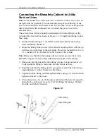
Page 20: ...ts HEPA filtered air back into the laboratory YOU MUST RECONFIGURE IT FOR THIS INSTALLATION These instructions follow Connecting the Axiom to an Exhaust System a Mechanical configuration 1 Using an ap...

Page 21: ...show the first level menu Select Service menu by pressing the or buttons until the Service is highlighted Press OK to accept that option or press Menu to return to the previous menu level Menu Display...

Page 22: ...TION IS SELECTED Press OK to continue 5 The second screen allows you to set how long the blowers in the Axiom will continue to operate in the event of an exhaust system failure The interval can be pro...

Page 23: ...FIGURATION AS IT WAS SET AT THE FACTORY Press OK to return to the first Configuration screen The unit is now properly configured for operation connected to an exhaust system In this mode the unit will...

Page 24: ...the studs on the right side Hand tighten the wing nuts to secure it as shown in figure 3 2a 2 Disconnect the Axiom s exhaust collar from the exhaust system and cap the building s exhaust connection i...

Page 25: ...show the first level menu Select Service menu by pressing the or buttons until the Service is highlighted Press OK to accept that option or press Menu to return to the previous menu level Menu Display...

Page 26: ...r 8 or 10 inches IT IS CRITICAL THAT THE YOU LEAVE THE SASH HEIGHT AS IT WAS SET AT THE FACTORY UNLESS YOU WISH TO RECERTIFY THE CABINET AT ITS NEW SETTING 6 The fourth screen allows you to select whe...

Page 27: ...rom the body of the portal by either pressing it through from the outside or by carefully inserting a spatula or similar device between the sealing plug and the body of the portal and prying the plug...

Page 28: ...ess steel cover that is sealed over the drain mounting holes Scrape out remaining sealant that is around the holes 6 Apply a light coating of silicone sealant user supplied to the mounting surface of...

Page 29: ...n NSF International ANSI Standard Number 49 in effect when the cabinet was manufactured Downflow Velocity Profile Test Inflow Velocity Test Airflow Smoke Patterns HEPA Filter Leak Test Inlet Relief Va...

Page 30: ...rinciples Filtration and retention of particulates by High Efficiency Particulate Air HEPA filter s Laminar airflow Directional airflow The Chem ZoneTM directly exhausted work zone The major component...

Page 31: ...filter are quantified and this establishes the efficiency of the filter Thus the filters used in the Axiom cabinets are at least 99 99 efficient in removing particles 0 3 micron Note The HEPA filter...

Page 32: ...a uniform velocity In practice the laminar downflow of air in the cabinet captures any aerosol generated in the work area of the cabinet and directs it to the HEPA filters In order to be true laminar...

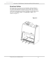
Page 33: ...n biosafety cabinet performance Air is drawn into the front of the cabinet at the front grille This curtain of air makes it more difficult for aerosols to escape out of the work area of the cabinet an...

Page 34: ...The central portion of the work surface is surrounded by grilles on the sides front and back Air entering these grilles is drawn to the Exhaust HEPA filter and when the cabinet is connected to an exh...

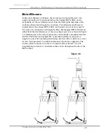
Page 35: ...and it draws the air in the center of the work area and pushes it through the filter discharging HEPA filtered air either back into the laboratory or into an exhaust system As shown in Figure 4 5 Both...

Page 36: ...ed proteins or metals or by other UV opaque substances protecting the target nucleic acid Because of its limitations UV light should be used as an adjunct to good surface disinfection practices In ord...

Page 37: ...t and stand overturning If your application requires loading more than 50 lbs contact Labconco s Product Service Department at 800 821 5525 or 816 333 8811 for assistance Ensure that the cabinet is co...

Page 38: ...afety cabinet Avoid splashing the disinfecting solution on skin or clothing Ensure adequate ventilation Carefully follow the disinfectant s safety instructions Always dispose of disinfecting solutions...

Page 39: ...operate the cabinet The System Reset Switch Blower Startup Sequence To ensure proper protection during blower startup the Axiom will always start its exhaust blower first When the exhaust blower reac...

Page 40: ...irst 60 seconds of operation After 60 seconds the default display screen will appear The display provides a clock the life remaining for both filters the cabinet s current status inflow velocities if...

Page 41: ...tive Protection Mode When connected to an exhaust system and the flow drops below acceptable limits this screen will appear When the timer reaches 0 the supply blower will shut off and the exhaust fan...

Page 42: ...the alarm and defeat the muting of the alarm The safety interlock system senses when the sash is closed and allows the optional ultraviolet UV lamp to operate only when the sash is closed to protect...

Page 43: ...sumes normal operation Pressing this button overrides Smart Start and Night Smart operation Light Button Turns the fluorescent lamps on or off Closing the sash automatically turns the lights off When...

Page 44: ...ore it shuts off NOTE When you are in the menu mode if a selection is not made within 30 seconds the display will reset back to display mode Keypad operations are shown as blue bold italic Menu screen...

Page 45: ...e MyLogic option it will turn blue when selected Press OK to enter the first MyLogic screen OK Using the and buttons on the touchpad highlight set the clock it will turn white when selected Press OK t...

Page 46: ...on for the fluorescent light if you want the lights to turn on every time you raise the sash select turn on and then press OK If stay off is selected then the lights must be manually turned on from th...

Page 47: ...erational parameters Please note all Settings screens have a green background Using the and buttons on the touchpad highlight the Settings option it will turn green when selected Press OK to enter the...

Page 48: ...tings menu screen use the and buttons on the touchpad to highlight the Security Lock option it will turn white when selected Press OK to enter the Security Lock screen Using the and buttons on the tou...

Page 49: ...and buttons on the touchpad to highlight the UV Settings option it will turn white when selected Press OK to enter the UV Settings screen Using the and buttons on the touchpad highlight UV Hourmeter i...

Page 50: ...by trained certification personnel as part of the certification or service procedures All of the screens have a yellow background and those portions of the Service Menu screens that can alter the per...

Page 51: ...outlet Removal of the work surface or grille during operation Resetting the Airflow Alert System The Airflow Alert automatically resets to normal operation once the motor speed has stabilized Working...

Page 52: ...proximately 22 6 inches or 574 mm Mute the alarm by depressing the OK Mute switch Wipe down the interior surfaces of the cabinet with 70 ethanol or a suitable disinfectant and allow to dry Loading Mat...

Page 53: ...pening during use Avoid the use of an open flame Use disposable labware or an electric incinerator as alternatives Use proper aseptic technique Avoid using techniques or procedures that disrupt the ai...

Page 54: ...catch located at the rear of the work area beneath the work pan Dispose of rubber gloves appropriately and have lab coat laundered properly Wash hands and arms thoroughly with germicidal soap Shutdow...

Page 55: ...Department at 800 821 5525 or 816 333 8811 Do NOT contact blower wheel while still in motion NE PAS tre en contact avec la rou du ventilateur tant qu il est en marche Routine Maintenance Schedule Week...

Page 56: ...urface must be thoroughly decontaminated before removing it from the cabinet 1 Lift either of the wing work surfaces up by grasping the knob handles at either front corner 2 This will lift up the cent...

Page 57: ...its back edge until the front edge of the work surface engages the catch located on the back wall of the work area 3 Lift and pull both wing work surfaces out 4 Reinstall the wing work surfaces by eng...

Page 58: ...2 At one end of the grille grip the front of grille with one hand and the back with the other hand Pivot that end of the grille upward and inward paralleling the angle of the sash as shown in Figure...

Page 59: ...shown in Figure 6 3 They are located on the bottom corners of the front dress panel 2 Swing the bottom of the dress panel out to clear the fluorescent light and then lift the front dress panel straig...

Page 60: ...he UV lamp timer The UV lamp and the work area of the cabinet must be thoroughly decontaminated before removing the lamp 1 Start the cabinet and let it operate for 5 minutes 2 Raise the sash to its fu...

Page 61: ...prepared for storage Note The cabinet should not be stored in areas of excess humidity or temperature extremes If the cabinet is moved during storage it must be recertified before use 1 Close the sas...

Page 62: ...lugged into outlet Plug the biosafety cabinet into appropriate electrical service Check connection to control box on top of cabinet System Reset Switch is Off Turn on the System Reset Switch Circuit b...

Page 63: ...s dim or flickering Lamp s are defective Replace defective lamp s Lamp wiring is disconnected Inspect lamp wiring Defective lamp ballast Replace lamp ballast UV light not working Sash is open Close sa...

Page 64: ...binet Improper technique or procedure for the biosafety cabinet See Use of the cabinet section in the manual Restriction of the return air slots or grille blockage of the exhaust outlet Ensure that al...

Page 65: ...acement accessory parts Biosafety Cabinet Replacement Parts Item Quantity Part No Description 1 1 3838901 Exhaust HEPA Filter 4 ft 1A 1 3838903 Exhaust HEPA Filter 6 ft 2 1 3838401 Supply HEPA Filter...

Page 66: ...Appendix A Components Product Service 1 800 522 7658 60 Original instructions 1 2 3 4 A 1...

Page 67: ...Original instructions Product Service 1 800 522 7658 61 Appendix B Dimensions 4 foot models All dimensions in inches cm B 1...

Page 68: ...Appendix B Dimensions Product Service 1 800 522 7658 62 Original instructions Dimensions 6 foot models All dimensions in inches cm B 2...

Page 69: ...Amps 230VAC Automatic Thermal Protection Environmental Conditions Indoor use only Ambient temperature range 41 to 104 F 5 to 40 C Maximum relative humidity 80 for temperatures up to 88 F 31 C decreas...

Page 70: ...Service 1 800 522 7658 64 Appendix D Accessories Labconco offers a full line of accessories to enhance your Axiom s operation and usability For a complete list of these accessories please consult our...

Page 71: ...3 3838403 Exhaust HEPA Data Labconco P N 3838511 3838511 3838513 3838513 Fluorescent UV Lamp Data Fluorescent Lamps 2 each F32T8 TL741 F32T8 TL741 F40T8 SP41 F40T8 SP41 UV Lamp G30T8 G30T8 G30T8 G30T8...

Reviews: