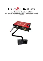
Rub
Rail
The rub rail is installed on the front of the tub. To install the rub rail, perform the following:
1. Slide the rub rail into the rub rail retaining slots on the case, ensuring the rub rail is level
with the case.
Case
Temperature
Display
Note:
There are several ways to review the case temperature. This includes an analog
(dial) display, a digital display, or electronically monitoring. This procedure is for
installation of the analog or digital display.
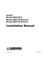
Analog Case Temperature Display and Probe
When equipped with an analog case temperature display, the display is located on the inside, top
of the case. To install the analog case temperature display, perform the following:
Caution:
Use caution when installing the case temperature display and probe into the
case. Ensure wiring is not accidently pinched between the case and the case
temperature display as the gage may not function properly.
Note:
The probe for the analog case temperature display is an integral part of the
display.
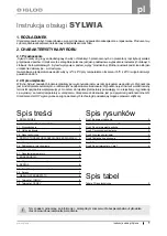
Analog Case Temperature Display and Probe
1. Connect electrical pigtail.
INSTALLATION/ASSEMBLY
78
Summary of Contents for 6RLG3
Page 3: ...2 6 2006 2 Addendum Ballast Relocation 2 ...
Page 5: ...2 6 2006 4 Addendum Ballast Relocation Wiring Diagram Both Canopy and Raceway 4 ...
Page 6: ...2 6 2006 5 Addendum Ballast Relocation Wiring Diagram for Canopy Light 5 ...
Page 9: ...Plan Views and Cross Sections D6L D6 D6H 8 ...
Page 10: ...D6RL D6R 9 ...
Page 11: ...QD6 10 ...
Page 34: ...D6 Electrical Model Table QD6 1 3 04 Through D6H 1 3 6 UNIT INSTALLATION 33 ...
Page 35: ...D6 Electrical Model Table D6H 1 3 6 Through D6R 1 3 4 UNIT INSTALLATION 34 ...
Page 36: ...D6 Electrical Model Table D6R 1 3 4 Through D6RL G 1 6 UNIT INSTALLATION 35 ...
Page 39: ...Wiring Diagram UNIT INSTALLATION 38 ...
Page 40: ...Wiring Diagram Canopy One 1 and Two 2 Light Rows UNIT INSTALLATION 39 ...
Page 41: ...Wiring Diagram Canopy Two 2 and Three 3 Light Rows UNIT INSTALLATION 40 ...
Page 42: ...Wiring Diagram Canopy Two 2 Light Rows and Nose Light UNIT INSTALLATION 41 ...
Page 43: ...Wiring Diagram Off Cycle Defrost UNIT INSTALLATION 42 ...